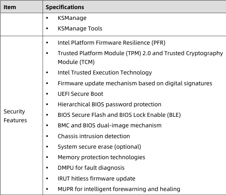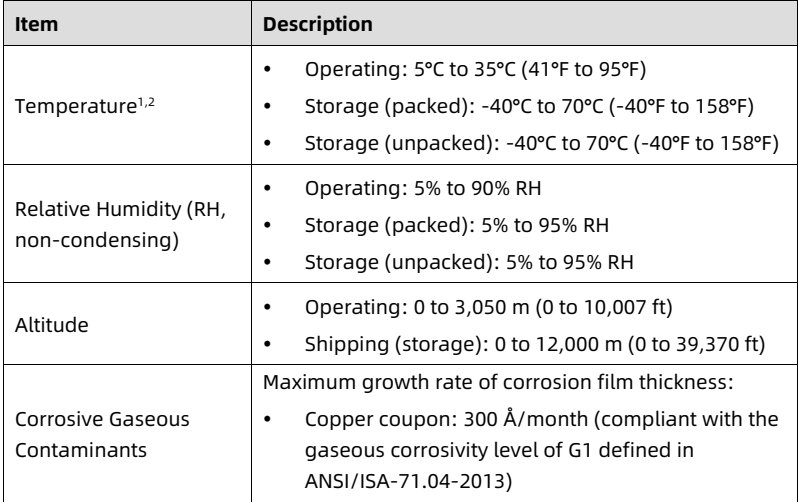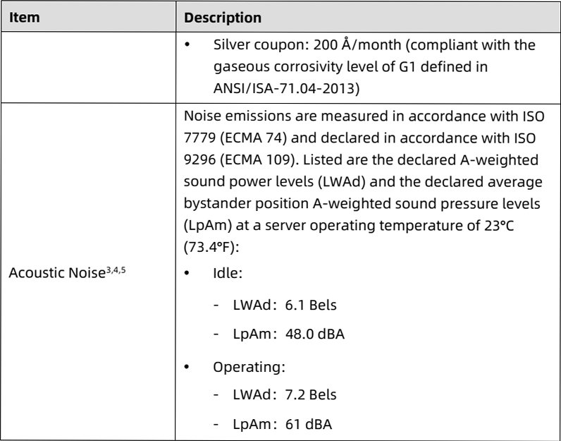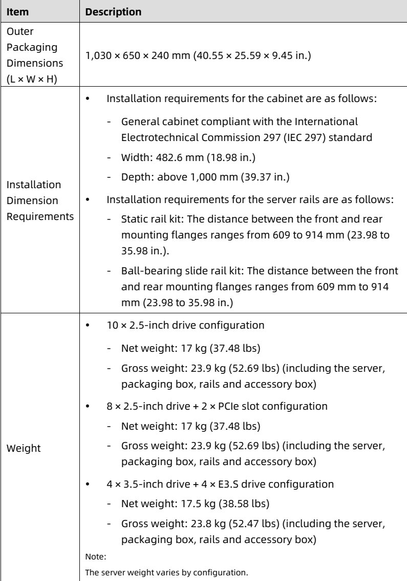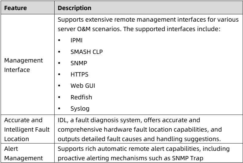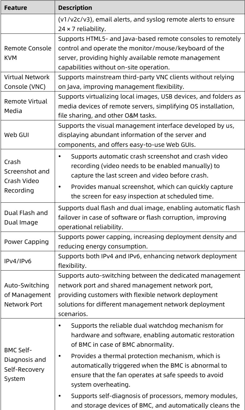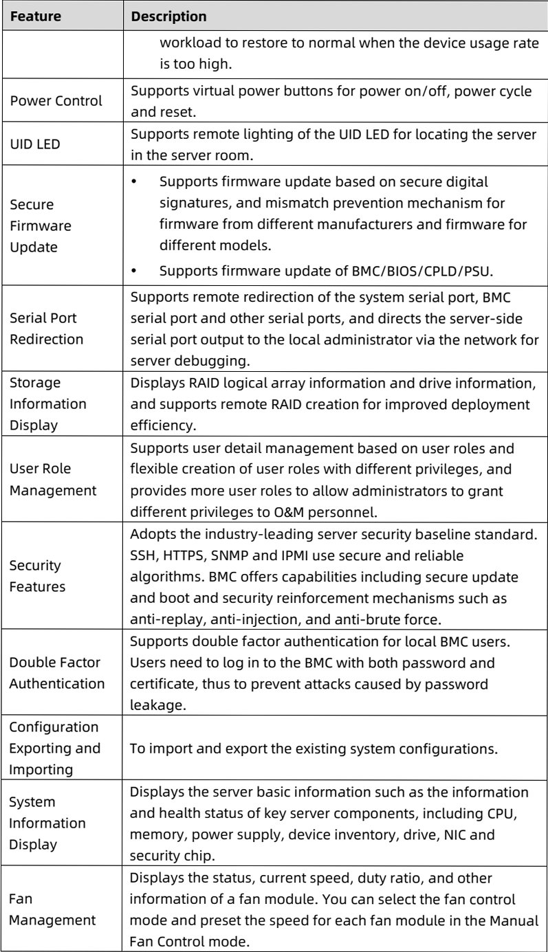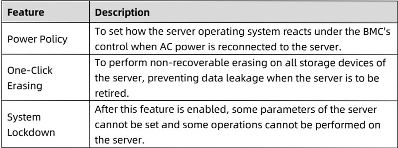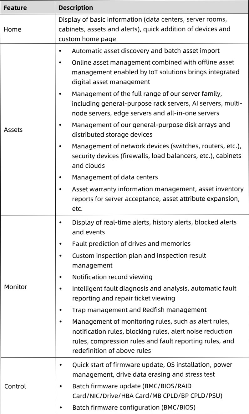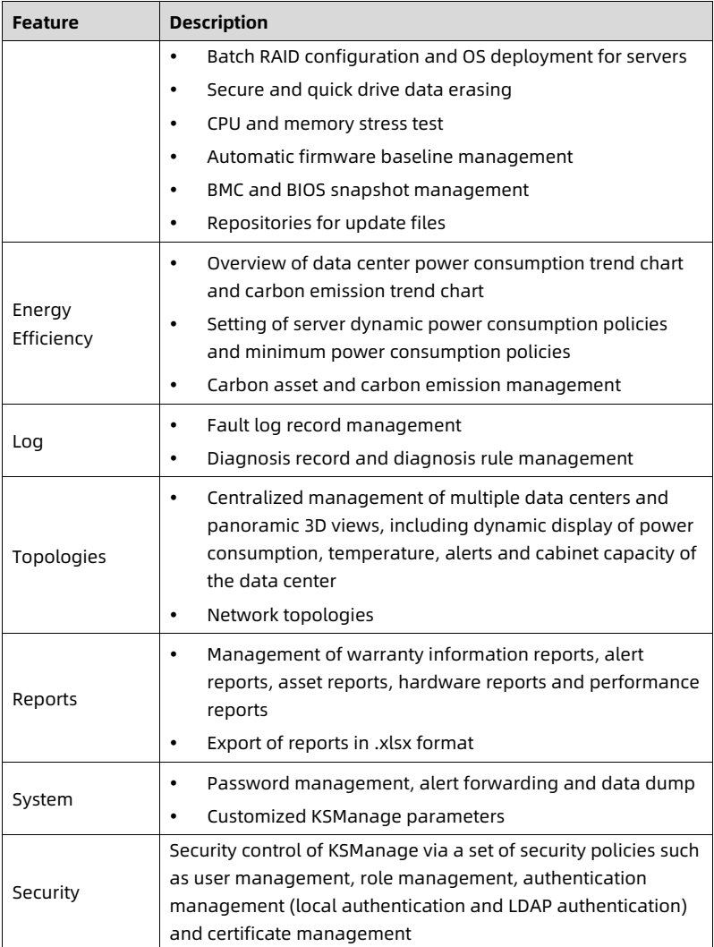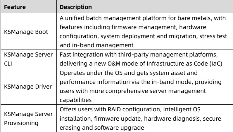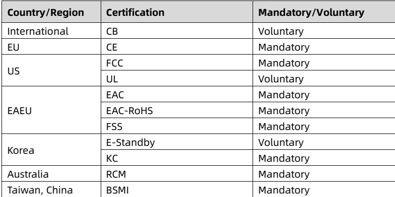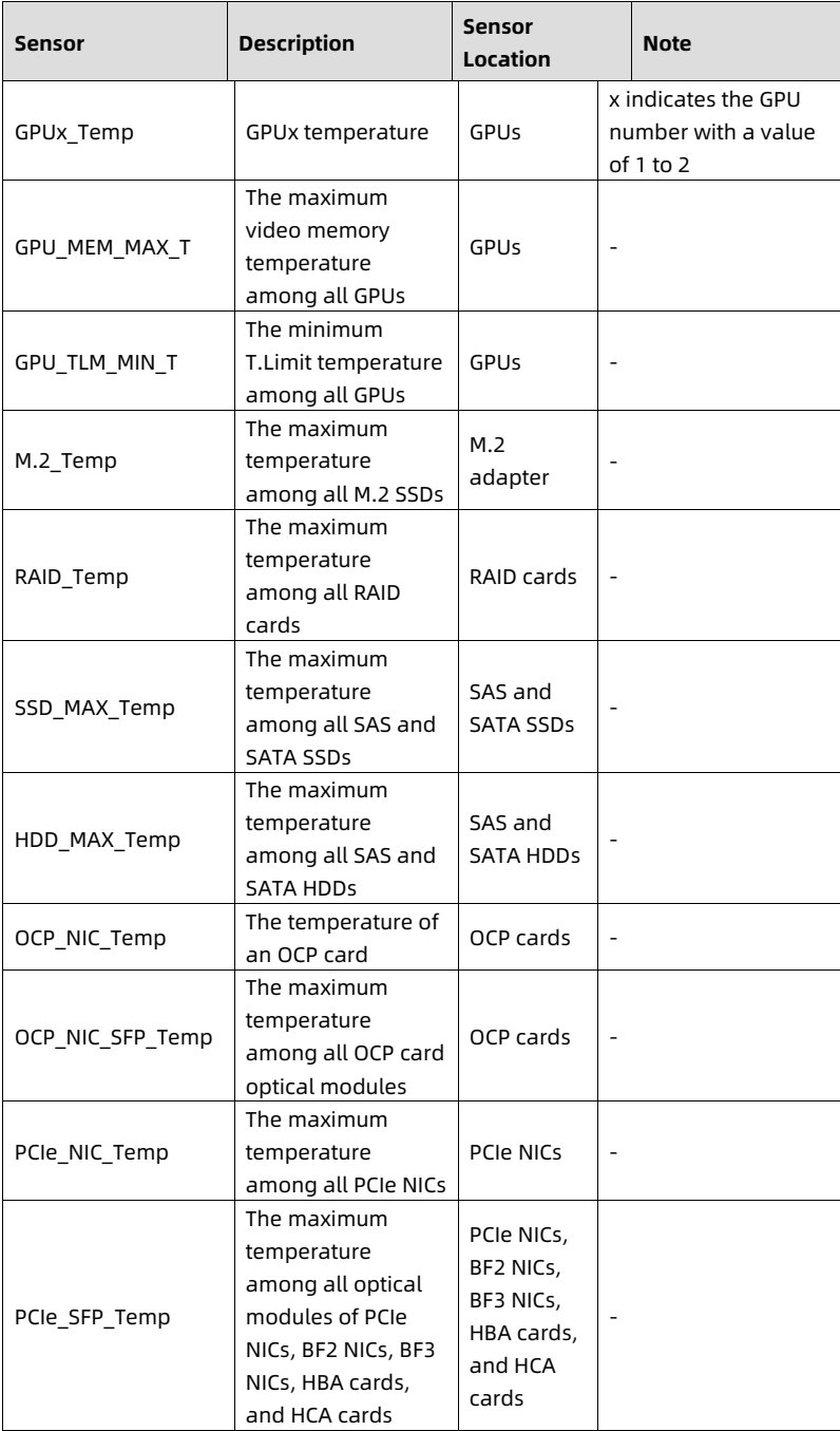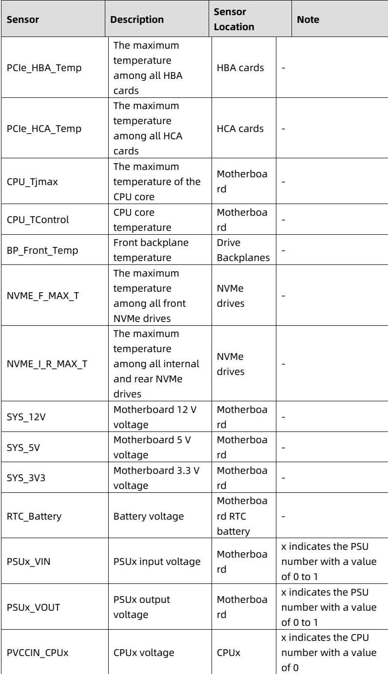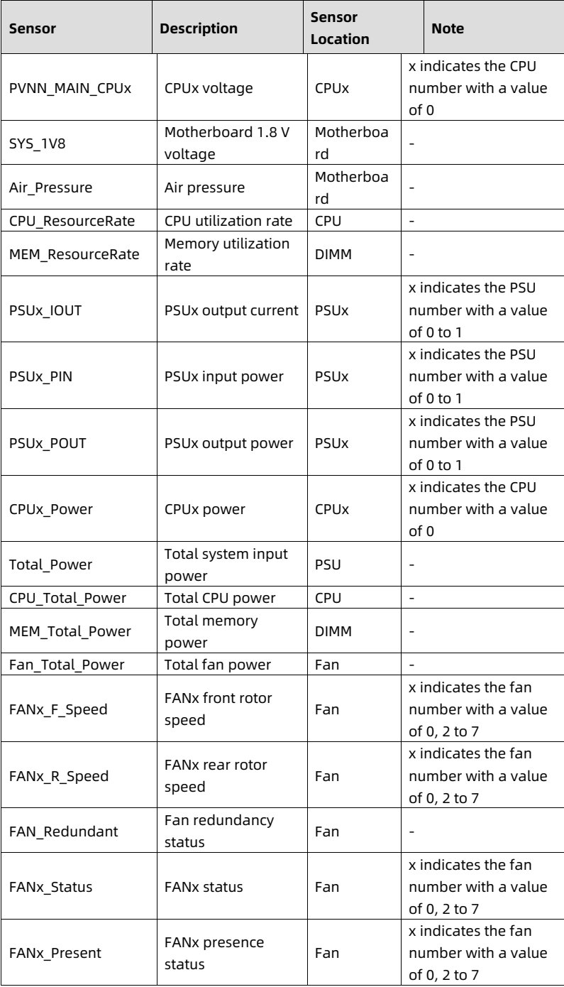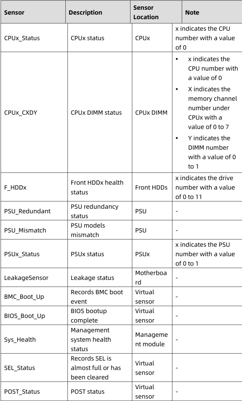
# Aivres KR1180 white paper (parsed)

Parsed from Aivres's PDF https://aivres.com/wp-content/uploads/Aivres-White-Paper-KR1180-X3-v1.pdf on 2026-10-15 (91 pages; OCR and table reconstruction by Reducto; tables are HTML inside this Markdown, images are figure crops from the PDF). Specifications belong to Aivres and are subject to change without notice; the PDF is the authority.

Products: [kr1180-x3](https://aivres.upstation.io/p/kr1180-x3)

---


<!-- page: 1 -->
<figure style="margin: 1rem 0; padding: 0.6rem; background: rgba(255,255,255,0.04); border-radius: 4px;">
  <img src="images/reducto/p001_figure_0001.jpg" alt="figure p1" style="max-width: 100%; max-height: 480px; display: block; margin: 0 auto;" />
  <figcaption style="font-size: 0.78rem; color: rgba(255,255,255,0.55); text-align: center; margin-top: 0.5rem;">AIVRES</figcaption>
</figure>

<b>White Paper for</b>
<b>KR1180V3 Series Servers</b>

<b>Powered by Intel Processors</b>

For KR1180-X3-A0-R0-00

Document Version: V1.0

Release Date: April 28, 2025

<!-- page: 2 -->
Copyright © 2025 KAYTUS SYSTEMS PTE. LTD. All rights reserved.

No part of this document may be reproduced or transmitted in any form or by any means without our prior written consent.

<b>Applicable Model</b>

<b>Model</b>: KR1180-X3-A0-R0-00
<b>Maintenance</b>: Rear access
<b>Cooling</b>: Air cooling

<b>Technical Support</b>

Global Service Hotline: (+1) 844-912-0007
Address: 1501 McCarthy Blvd, Milpitas, CA 95035
AIVRES SYSTEMS INC.
Website: <u>https://aivres.com</u>
Email: <u>serversupport@aivres.com</u>

<!-- page: 3 -->
<b>Environmental Protection</b>

Please dispose of product packaging by recycling at a local recycling center for a greener planet.

<b>Trademarks</b>

All the trademarks or registered trademarks mentioned herein may be the property of their respective holders. This document does not mark any product or brand with the symbol ® or ™.

<b>Security Statement</b>

We are intensely focused on server product safety and have placed a high priority on this. For a better understanding of our server products, carefully read through the following security risk statements.

• When servers are to be repurposed or retired, we recommend that you restore their firmware factory settings, delete information and clear logs from BIOS and BMC to protect data privacy. Meanwhile, we recommend that you wipe the drive data thoroughly and securely with trusted erasing tools. You can use KSManage Server Provisioning. Contact us for specific server models to which KSManage Server Provisioning is applicable.

• For server open source software statements, please contact us.

• Some interfaces and commands for production, assembly and return-to-depot, and advanced commands for locating faults, if used improperly, may cause equipment abnormality or business interruption. This is not described herein. Please contact us for such information.

• External ports of our servers do not use private protocols for communication.

• Our products will not initiatives obtain or use your personal data. Only when you consent to use certain functions or services, some personal data such as IP address and email address for alerts may be obtained or used during business operation or fault location. We have implemented necessary measures on product functions to ensure personal data security throughout the data lifecycle, including but not limited to data collection, storage, use, transmission, and destruction. Meanwhile, you are obligated to establish necessary user privacy policies in accordance with applicable national/regional laws and regulations to fully protect user personal data.

• Committed to product data security, we have implemented necessary measures on product functions to protect system operation and security data throughout its lifecycle in strict accordance with relevant laws, regulations and supervision

<!-- page: 4 -->
requirements. As the owner of system operation and security data, you are obligated to establish necessary data security policies and take adequate measures in accordance with applicable national/regional laws and regulations to fully protect system operation and security data.

• We will remain committed to the safety of our products and solutions to achieve better customer satisfaction. We have established emergency response procedures and action plans for security vulnerabilities, so that product safety issues can be dealt with in a timely manner. Please contact us for any safety problems found or necessary support on security vulnerabilities when using our products.

<b>Disclaimer</b>

The purchased products, services, and features shall be bound by the contract made between the customer and us. All or part of the products, services and features described herein may not be within your purchase or usage scope. Unless otherwise agreed in the contract, we make no express or implied statement or warranty on the contents herein. Images provided herein are for reference only and may contain information or features that do not apply to your purchased model. This document is only used as a guide. We shall not be liable for any damage, including but not limited to loss of profits, loss of information, interruption of business, personal injury, or any consequential damage incurred before, during, or after your use of our products. We assume you have sufficient knowledge of servers and are well trained in protecting yourself from personal injury or preventing product damage during operation and maintenance. The information in this document is subject to change without notice.

<!-- page: 5 -->
*Preface*

<b>Abstract</b>

This document describes the KR1180V3 Intel-based server's appearance, features, performance parameters, and software and hardware compatibility, providing in-depth information of the server.

<b>Intended Audience</b>

This document is intended for pre-sales engineers.

<b>Symbol Conventions</b>

The symbols that may be found in this document are defined as follows.

<table>
<thead>
<tr>
<th> <b>Symbol</b> </th>
<th> <b>Description</b> </th>
</tr>
</thead>
<tbody>
<tr>
<td> DANGER </td>
<td> A potential for serious injury, or even death if not properly handled </td>
</tr>
<tr>
<td> WARNING </td>
<td> A potential for minor or moderate injury if not properly handled </td>
</tr>
<tr>
<td> CAUTION </td>
<td> A potential loss of data or damage to equipment if not properly handled </td>
</tr>
<tr>
<td> IMPORTANT </td>
<td> Operations or information that requires special attention to ensure successful installation or configuration </td>
</tr>
<tr>
<td> NOTE </td>
<td> Supplementary description of document information </td>
</tr>
</tbody>
</table>

<details style="margin: 0.3rem 0 1rem; padding: 0.4rem 0.6rem; background: rgba(255,255,255,0.03); border-radius: 4px; border: 1px solid rgba(255,255,255,0.08);">
  <summary style="cursor: pointer; font-size: 0.75rem; color: rgba(255,255,255,0.55);">📷 view source screenshot for verification (page 5)</summary>
  <img src="images/reducto/p005_table_0044.jpg" alt="table source p5" style="max-width: 100%; margin-top: 0.6rem; display: block;" />
</details>

<b>Revision History</b>

<table>
<thead>
<tr>
<th> Version </th>
<th> Date </th>
<th> Description of Changes </th>
</tr>
</thead>
<tbody>
<tr>
<td> V1.0 </td>
<td> 2025/04/28 </td>
<td> Initial release </td>
</tr>
</tbody>
</table>

<details style="margin: 0.3rem 0 1rem; padding: 0.4rem 0.6rem; background: rgba(255,255,255,0.03); border-radius: 4px; border: 1px solid rgba(255,255,255,0.08);">
  <summary style="cursor: pointer; font-size: 0.75rem; color: rgba(255,255,255,0.55);">📷 view source screenshot for verification (page 5)</summary>
  <img src="images/reducto/p005_table_0046.jpg" alt="table source p5" style="max-width: 100%; margin-top: 0.6rem; display: block;" />
</details>

<!-- page: 6 -->
<b>Table of Contents</b>

1 Product Overview ... 1
2 Features ... 2
2.1 Scalability and Performance ... 2
2.2 Availability and Serviceability ... 3
2.3 Manageability and Security... 4
2.4 Energy Efficiency ... 6
3 System Parts Breakdown... 8
4 System Logical Diagram... 9
5 Hardware Description ... 10
5.1 Front Panel... 10
5.1.1 4 × 3.5-Inch Drive + 4 × E3.S Drive Configuration ... 10
5.1.2 8 × 2.5-Inch Drive + 2 × PCIe Slot Configuration ... 11
5.1.3 10 × 2.5-Inch Drive Configuration ... 11
5.2 Rear Panel... 12
5.2.1 2 × PCIe Slot Configuration ... 12
5.2.2 3 × PCIe Slot Configuration ... 12
5.3 LEDs and Buttons ... 13
5.4 Port Description... 16
5.5 Processor ... 16
5.6 DDR5 DIMMs... 17
5.6.1 Identification ... 17
5.6.2 Memory Subsystem Architecture ... 18
5.6.3 Compatibility ... 19
5.6.4 DIMM Population Rules... 20
5.6.5 DIMM Slot Layout... 21

<!-- page: 7 -->
5.7 Storage ... 22
5.7.1 Drive Configurations ... 22
5.7.2 Drive Numbering ... 23
5.7.3 Drive LEDs... 24
5.7.4 RAID Cards ... 26
5.8 Network ... 26
5.9 I/O Expansion ... 26
5.9.1 PCIe Expansion Cards ... 26
5.9.2 PCIe Slot Locations... 27
5.9.3 PCIe Riser Module ... 28
5.9.4 PCIe Slot Description ... 29
5.10 PSUs... 31
5.10.1 PSU Locations ... 31
5.10.2 PSU LED ... 31
5.11 Fan Module ... 32
5.12 LCD Module ... 33
5.12.1 Function... 33
5.12.2 Interface ... 35
5.13 Boards... 35
5.13.1 Motherboard ... 36
5.13.2 Drive Backplanes ... 37
6 Product Specifications ... 40
6.1 Technical Specifications ... 40
6.2 Environmental Specifications... 42
6.3 Physical Specifications ... 44
7 Operating System and Hardware Compatibility ... 46
7.1 Supported Operating System ... 46

<!-- page: 8 -->
7.2 Hardware Compatibility 47
7.2.1 CPU Specifications 47
7.2.2 DIMM Specifications 47
7.2.3 Drive Specifications 47
7.2.4 SAS/RAID Card Specifications 48
7.2.5 NIC Specifications 48
7.2.6 HCA Card Specifications 49
7.2.7 PSU Specifications 49
8 Regulatory Information 51
8.1 Safety 51
8.1.1 General 51
8.1.2 Personal Safety 51
8.1.3 Equipment Safety 53
8.1.4 Transportation Precautions 54
8.1.5 Manual Handling Weight Limits 54
9 Limited Warranty 55
9.1 Warranty Service 55
9.1.1 Remote Technical Support 55
9.1.2 RMA Service 56
9.1.3 ARMA Service 56
9.1.4 9 × 5 × NBD Onsite Service 56
9.1.5 24 × 7 × 4 Onsite Service 57
9.2 Our Service SLA 57
9.3 Warranty Exclusions 57
10 System Management 59
10.1 Intelligent Management System BMC 59
10.2 KSManage 62

<!-- page: 9 -->
10.3 KSManage Tools... 64
11 Certification ... 66
12 Appendix A... 67
12.1 Thermal Restrictions... 67
12.2 Power/Performance Profiles ... 68
12.3 Model... 69
12.4 RAS Features ... 69
12.5 Sensor List... 69
13 Appendix C Acronyms and Abbreviations ... 75
13.1 A - E ... 75
13.2 F - J... 77
13.3 K - O ... 78
13.4 P - T... 80
13.5 U - Z ... 82

<!-- page: 10 -->
White Paper for KAYTUS KR1180V3 Series Servers_Powered by Intel Processors

1 Product Overview

The KR1180V3 Intel-based system is a 1U single-socket rack server powered by the Intel Xeon 6 processor built on the Birch Stream platform, meeting requirements for medium to low computing power and storage. Exceptional product specifications, a low cost, and a high performance per watt ratio bring customers a low-cost platform upgrade alternative, tackling high TCO and cross-NUMA problems. Configured with rich IO CPU SKUs, it offers expandability comparable to dual-socket configurations and supports all-flash and GPU configurations.

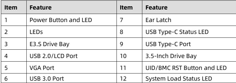
Figure 1-1 Appearance of 4 × 3.5-Inch Drive + 4 × E3.S Drive Configuration

![figure](images/reducto/p010_figure_0066.jpg)

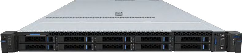
Figure 1-2 Appearance of 10 × 2.5-Inch Drive Configuration

<figure style="margin: 1rem 0; padding: 0.6rem; background: rgba(255,255,255,0.04); border-radius: 4px;">
  <img src="images/reducto/p010_figure_0068.jpg" alt="figure p10" style="max-width: 100%; max-height: 480px; display: block; margin: 0 auto;" />
  <figcaption style="font-size: 0.78rem; color: rgba(255,255,255,0.55); text-align: center; margin-top: 0.5rem;">E</figcaption>
</figure>

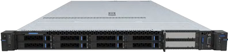
Figure 1-3 Appearance of 8 × 2.5-Inch Drive + 2 × PCIe Slot Configuration

<figure style="margin: 1rem 0; padding: 0.6rem; background: rgba(255,255,255,0.04); border-radius: 4px;">
  <img src="images/reducto/p010_figure_0070.jpg" alt="figure p10" style="max-width: 100%; max-height: 480px; display: block; margin: 0 auto;" />
  <figcaption style="font-size: 0.78rem; color: rgba(255,255,255,0.55); text-align: center; margin-top: 0.5rem;">196969696</figcaption>
</figure>

1

<!-- page: 11 -->
White Paper for KAYTUS KR1180V3 Series Servers_Powered by Intel Processors

<figure style="margin: 1rem 0; padding: 0.6rem; background: rgba(255,255,255,0.04); border-radius: 4px;">
  <img src="images/reducto/p011_figure_0075.jpg" alt="figure p11" style="max-width: 100%; max-height: 480px; display: block; margin: 0 auto;" />
  <figcaption style="font-size: 0.78rem; color: rgba(255,255,255,0.55); text-align: center; margin-top: 0.5rem;">2 Features</figcaption>
</figure>

<b>2.1 Scalability and Performance</b>

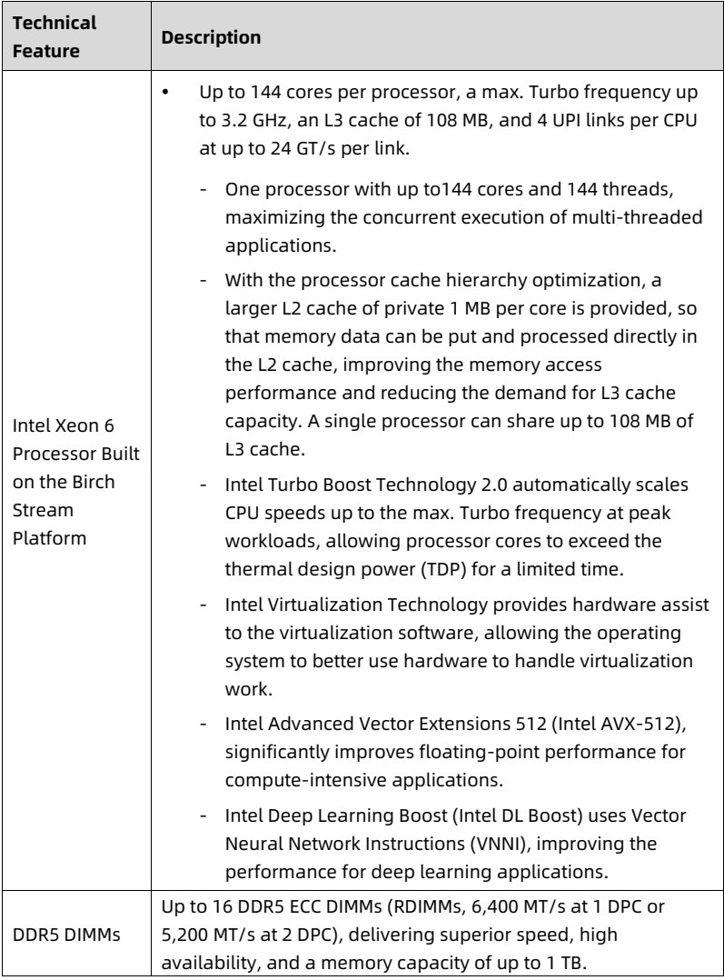
Table 2-1 Scalability and Performance

<table>
<thead>
<tr>
<th> Technical Feature </th>
<th> Description </th>
</tr>
</thead>
<tbody>
<tr>
<td> Intel Xeon 6 Processor Built on the Birch Stream Platform </td>
<td> • Up to 144 cores per processor, a max. Turbo frequency up to 3.2 GHz, an L3 cache of 108 MB, and 4 UPI links per CPU at up to 24 GT/s per link.
- One processor with up to144 cores and 144 threads, maximizing the concurrent execution of multi-threaded applications.
- With the processor cache hierarchy optimization, a larger L2 cache of private 1 MB per core is provided, so that memory data can be put and processed directly in the L2 cache, improving the memory access performance and reducing the demand for L3 cache capacity. A single processor can share up to 108 MB of L3 cache.
- Intel Turbo Boost Technology 2.0 automatically scales CPU speeds up to the max. Turbo frequency at peak workloads, allowing processor cores to exceed the thermal design power (TDP) for a limited time.
- Intel Virtualization Technology provides hardware assist to the virtualization software, allowing the operating system to better use hardware to handle virtualization work.
- Intel Advanced Vector Extensions 512 (Intel AVX-512), significantly improves floating-point performance for compute-intensive applications.
- Intel Deep Learning Boost (Intel DL Boost) uses Vector Neural Network Instructions (VNNI), improving the performance for deep learning applications. </td>
</tr>
<tr>
<td> DDR5 DIMMs </td>
<td> Up to 16 DDR5 ECC DIMMs (RDIMMs, 6,400 MT/s at 1 DPC or 5,200 MT/s at 2 DPC), delivering superior speed, high availability, and a memory capacity of up to 1 TB. </td>
</tr>
</tbody>
</table>

<details style="margin: 0.3rem 0 1rem; padding: 0.4rem 0.6rem; background: rgba(255,255,255,0.03); border-radius: 4px; border: 1px solid rgba(255,255,255,0.08);">
  <summary style="cursor: pointer; font-size: 0.75rem; color: rgba(255,255,255,0.55);">📷 view source screenshot for verification (page 11)</summary>
  <img src="images/reducto/p011_table_0078.jpg" alt="table source p11" style="max-width: 100%; margin-top: 0.6rem; display: block;" />
</details>

2

<!-- page: 12 -->
White Paper for KAYTUS KR1180V3 Series Servers_Powered by Intel Processors

<table>
<thead>
<tr>
<th> Technical Feature </th>
<th> Description </th>
</tr>
</thead>
<tbody>
<tr>
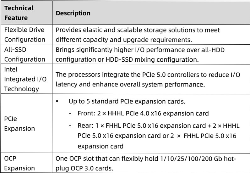
<td> Flexible Drive Configuration </td>
<td> Provides elastic and scalable storage solutions to meet different capacity and upgrade requirements. </td>
</tr>
<tr>
<td> All-SSD Configuration </td>
<td> Brings significantly higher I/O performance over all-HDD configuration or HDD-SSD mixing configuration. </td>
</tr>
<tr>
<td> Intel Integrated I/O Technology </td>
<td> The processors integrate the PCIe 5.0 controllers to reduce I/O latency and enhance overall system performance. </td>
</tr>
<tr>
<td> PCIe Expansion </td>
<td> • Up to 5 standard PCIe expansion cards.
- Front: 2 × HHHL PCIe 4.0 x16 expansion card
- Rear: 1 × FHHL PCIe 5.0 x16 expansion card + 2 × HHHL PCIe 5.0 x16 expansion card or 2 × FHHL PCIe 5.0 x16 expansion card </td>
</tr>
<tr>
<td> OCP Expansion </td>
<td> One OCP slot that can flexibly hold 1/10/25/100/200 Gb hot-plug OCP 3.0 cards. </td>
</tr>
</tbody>
</table>

<details style="margin: 0.3rem 0 1rem; padding: 0.4rem 0.6rem; background: rgba(255,255,255,0.03); border-radius: 4px; border: 1px solid rgba(255,255,255,0.08);">
  <summary style="cursor: pointer; font-size: 0.75rem; color: rgba(255,255,255,0.55);">📷 view source screenshot for verification (page 12)</summary>
  <img src="images/reducto/p012_table_0083.jpg" alt="table source p12" style="max-width: 100%; margin-top: 0.6rem; display: block;" />
</details>

<b>2.2 Availability and Serviceability</b>

Table 2-2 Availability and Serviceability

<table>
<thead>
<tr>
<th> Technical Feature </th>
<th> Description </th>
</tr>
</thead>
<tbody>
<tr>
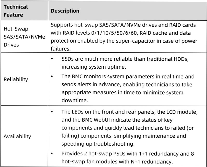
<td> Hot-Swap SAS/SATA/NVMe Drives </td>
<td> Supports hot-swap SAS/SATA/NVMe drives and RAID cards with RAID levels 0/1/10/5/50/6/60, RAID cache and data protection enabled by the super-capacitor in case of power failures. </td>
</tr>
<tr>
<td> Reliability </td>
<td> • SSDs are much more reliable than traditional HDDs, increasing system uptime.
• The BMC monitors system parameters in real time and sends alerts in advance, enabling technicians to take appropriate measures in time to minimize system downtime. </td>
</tr>
<tr>
<td> Availability </td>
<td> • The LEDs on the front and rear panels, the LCD module, and the BMC WebUI indicate the status of key components and quickly lead technicians to failed (or failing) components, simplifying maintenance and speeding up troubleshooting.
• Provides 2 hot-swap PSUs with 1+1 redundancy and 8 hot-swap fan modules with N+1 redundancy. </td>
</tr>
</tbody>
</table>

<details style="margin: 0.3rem 0 1rem; padding: 0.4rem 0.6rem; background: rgba(255,255,255,0.03); border-radius: 4px; border: 1px solid rgba(255,255,255,0.08);">
  <summary style="cursor: pointer; font-size: 0.75rem; color: rgba(255,255,255,0.55);">📷 view source screenshot for verification (page 12)</summary>
  <img src="images/reducto/p012_table_0086.jpg" alt="table source p12" style="max-width: 100%; margin-top: 0.6rem; display: block;" />
</details>

3

<!-- page: 13 -->
White Paper for KAYTUS KR1180V3 Series Servers_Powered by Intel Processors

<table>
<thead>
<tr>
<th> Technical Feature </th>
<th> Description </th>
</tr>
</thead>
<tbody>
<tr>
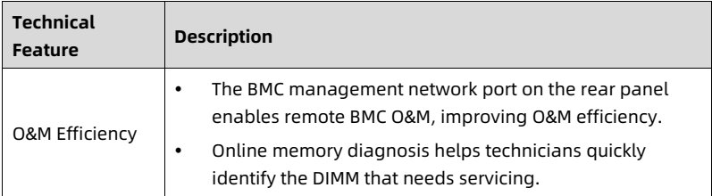
<td> O&amp;M Efficiency </td>
<td> • The BMC management network port on the rear panel enables remote BMC O&amp;M, improving O&amp;M efficiency.
• Online memory diagnosis helps technicians quickly identify the DIMM that needs servicing. </td>
</tr>
</tbody>
</table>

<details style="margin: 0.3rem 0 1rem; padding: 0.4rem 0.6rem; background: rgba(255,255,255,0.03); border-radius: 4px; border: 1px solid rgba(255,255,255,0.08);">
  <summary style="cursor: pointer; font-size: 0.75rem; color: rgba(255,255,255,0.55);">📷 view source screenshot for verification (page 13)</summary>
  <img src="images/reducto/p013_table_0091.jpg" alt="table source p13" style="max-width: 100%; margin-top: 0.6rem; display: block;" />
</details>

<b>2.3 Manageability and Security</b>

Table 2-3 Manageability and Security

<table>
<thead>
<tr>
<th> Technical Feature </th>
<th> Description </th>
</tr>
</thead>
<tbody>
<tr>
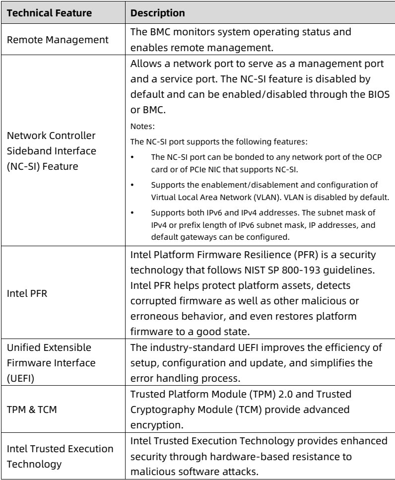
<td> Remote Management </td>
<td> The BMC monitors system operating status and enables remote management. </td>
</tr>
<tr>
<td> Network Controller Sideband Interface (NC-SI) Feature </td>
<td> Allows a network port to serve as a management port and a service port. The NC-SI feature is disabled by default and can be enabled/disabled through the BIOS or BMC.
Notes:
The NC-SI port supports the following features:
• The NC-SI port can be bonded to any network port of the OCP card or of PCIe NIC that supports NC-SI.
• Supports the enablement/disablement and configuration of Virtual Local Area Network (VLAN). VLAN is disabled by default.
• Supports both IPv6 and IPv4 addresses. The subnet mask of IPv4 or prefix length of IPv6 subnet mask, IP addresses, and default gateways can be configured. </td>
</tr>
<tr>
<td> Intel PFR </td>
<td> Intel Platform Firmware Resilience (PFR) is a security technology that follows NIST SP 800-193 guidelines. Intel PFR helps protect platform assets, detects corrupted firmware as well as other malicious or erroneous behavior, and even restores platform firmware to a good state. </td>
</tr>
<tr>
<td> Unified Extensible Firmware Interface (UEFI) </td>
<td> The industry-standard UEFI improves the efficiency of setup, configuration and update, and simplifies the error handling process. </td>
</tr>
<tr>
<td> TPM &amp; TCM </td>
<td> Trusted Platform Module (TPM) 2.0 and Trusted Cryptography Module (TCM) provide advanced encryption. </td>
</tr>
<tr>
<td> Intel Trusted Execution Technology </td>
<td> Intel Trusted Execution Technology provides enhanced security through hardware-based resistance to malicious software attacks. </td>
</tr>
</tbody>
</table>

<details style="margin: 0.3rem 0 1rem; padding: 0.4rem 0.6rem; background: rgba(255,255,255,0.03); border-radius: 4px; border: 1px solid rgba(255,255,255,0.08);">
  <summary style="cursor: pointer; font-size: 0.75rem; color: rgba(255,255,255,0.55);">📷 view source screenshot for verification (page 13)</summary>
  <img src="images/reducto/p013_table_0094.jpg" alt="table source p13" style="max-width: 100%; margin-top: 0.6rem; display: block;" />
</details>

4

<!-- page: 14 -->
White Paper for KAYTUS KR1180V3 Series Servers_Powered by Intel Processors

<table>
<thead>
<tr>
<th> Technical Feature </th>
<th> Description </th>
</tr>
</thead>
<tbody>
<tr>
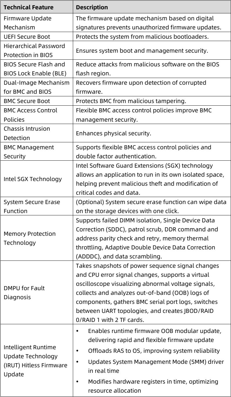
<td> Firmware Update Mechanism </td>
<td> The firmware update mechanism based on digital signatures prevents unauthorized firmware updates. </td>
</tr>
<tr>
<td> UEFI Secure Boot </td>
<td> Protects the system from malicious bootloaders. </td>
</tr>
<tr>
<td> Hierarchical Password Protection in BIOS </td>
<td> Ensures system boot and management security. </td>
</tr>
<tr>
<td> BIOS Secure Flash and BIOS Lock Enable (BLE) </td>
<td> Reduce attacks from malicious software on the BIOS flash region. </td>
</tr>
<tr>
<td> Dual-Image Mechanism for BMC and BIOS </td>
<td> Recovers firmware upon detection of corrupted firmware. </td>
</tr>
<tr>
<td> BMC Secure Boot </td>
<td> Protects BMC from malicious tampering. </td>
</tr>
<tr>
<td> BMC Access Control Policies </td>
<td> Flexible BMC access control policies improve BMC management security. </td>
</tr>
<tr>
<td> Chassis Intrusion Detection </td>
<td> Enhances physical security. </td>
</tr>
<tr>
<td> BMC Management Security </td>
<td> Supports flexible BMC access control policies and double factor authentication. </td>
</tr>
<tr>
<td> Intel SGX Technology </td>
<td> Intel Software Guard Extensions (SGX) technology allows an application to run in its own isolated space, helping prevent malicious theft and modification of critical codes and data. </td>
</tr>
<tr>
<td> System Secure Erase Function </td>
<td> (Optional) System secure erase function can wipe data on the storage devices with one click. </td>
</tr>
<tr>
<td> Memory Protection Technology </td>
<td> Supports failed DIMM isolation, Single Device Data Correction (SDDC), patrol scrub, DDR command and address parity check and retry, memory thermal throttling, Adaptive Double Device Data Correction (ADDDC), and data scrambling. </td>
</tr>
<tr>
<td> DMPU for Fault Diagnosis </td>
<td> Takes snapshots of power sequence signal changes and CPU error signal changes, supports a virtual oscilloscope visualizing abnormal voltage signals, collects and analyzes out-of-band (OOB) logs of components, gathers BMC serial port logs, switches between UART topologies, and creates JBOD/RAID 0/RAID 1 with 2 TF cards. </td>
</tr>
<tr>
<td> Intelligent Runtime Update Technology (IRUT) Hitless Firmware Update </td>
<td> • Enables runtime firmware OOB modular update, delivering rapid and flexible firmware update
• Offloads RAS to OS, improving system reliability
• Updates System Management Mode (SMM) driver in real time
• Modifies hardware registers in time, optimizing resource allocation </td>
</tr>
</tbody>
</table>

<details style="margin: 0.3rem 0 1rem; padding: 0.4rem 0.6rem; background: rgba(255,255,255,0.03); border-radius: 4px; border: 1px solid rgba(255,255,255,0.08);">
  <summary style="cursor: pointer; font-size: 0.75rem; color: rgba(255,255,255,0.55);">📷 view source screenshot for verification (page 14)</summary>
  <img src="images/reducto/p014_table_0099.jpg" alt="table source p14" style="max-width: 100%; margin-top: 0.6rem; display: block;" />
</details>

5

<!-- page: 15 -->
White Paper for KAYTUS KR1180V3 Series Servers_Powered by Intel Processors

<table>
<thead>
<tr>
<th> Technical Feature </th>
<th> Description </th>
</tr>
</thead>
<tbody>
<tr>
<td></td>
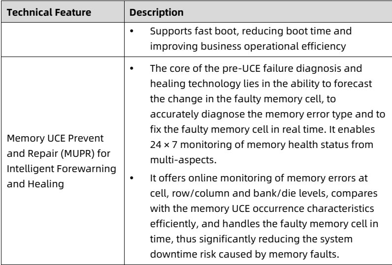
<td> • Supports fast boot, reducing boot time and improving business operational efficiency </td>
</tr>
<tr>
<td> Memory UCE Prevent and Repair (MUPR) for Intelligent Forewarning and Healing </td>
<td> • The core of the pre-UCE failure diagnosis and healing technology lies in the ability to forecast the change in the faulty memory cell, to accurately diagnose the memory error type and to fix the faulty memory cell in real time. It enables 24 × 7 monitoring of memory health status from multi-aspects.
• It offers online monitoring of memory errors at cell, row/column and bank/die levels, compares with the memory UCE occurrence characteristics efficiently, and handles the faulty memory cell in time, thus significantly reducing the system downtime risk caused by memory faults. </td>
</tr>
</tbody>
</table>

<details style="margin: 0.3rem 0 1rem; padding: 0.4rem 0.6rem; background: rgba(255,255,255,0.03); border-radius: 4px; border: 1px solid rgba(255,255,255,0.08);">
  <summary style="cursor: pointer; font-size: 0.75rem; color: rgba(255,255,255,0.55);">📷 view source screenshot for verification (page 15)</summary>
  <img src="images/reducto/p015_table_0104.jpg" alt="table source p15" style="max-width: 100%; margin-top: 0.6rem; display: block;" />
</details>

<b>2.4 Energy Efficiency</b>

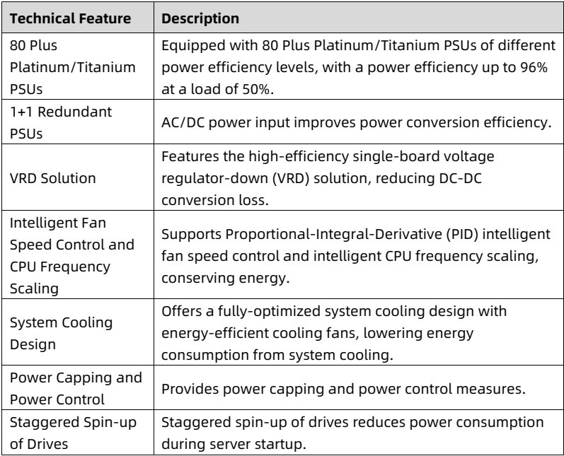
Table 2-4 Energy Efficiency

<table>
<thead>
<tr>
<th> <b>Technical Feature</b> </th>
<th> <b>Description</b> </th>
</tr>
</thead>
<tbody>
<tr>
<td> 80 Plus Platinum/Titanium PSUs </td>
<td> Equipped with 80 Plus Platinum/Titanium PSUs of different power efficiency levels, with a power efficiency up to 96% at a load of 50%. </td>
</tr>
<tr>
<td> 1+1 Redundant PSUs </td>
<td> AC/DC power input improves power conversion efficiency. </td>
</tr>
<tr>
<td> VRD Solution </td>
<td> Features the high-efficiency single-board voltage regulator-down (VRD) solution, reducing DC-DC conversion loss. </td>
</tr>
<tr>
<td> Intelligent Fan Speed Control and CPU Frequency Scaling </td>
<td> Supports Proportional-Integral-Derivative (PID) intelligent fan speed control and intelligent CPU frequency scaling, conserving energy. </td>
</tr>
<tr>
<td> System Cooling Design </td>
<td> Offers a fully-optimized system cooling design with energy-efficient cooling fans, lowering energy consumption from system cooling. </td>
</tr>
<tr>
<td> Power Capping and Power Control </td>
<td> Provides power capping and power control measures. </td>
</tr>
<tr>
<td> Staggered Spin-up of Drives </td>
<td> Staggered spin-up of drives reduces power consumption during server startup. </td>
</tr>
</tbody>
</table>

<details style="margin: 0.3rem 0 1rem; padding: 0.4rem 0.6rem; background: rgba(255,255,255,0.03); border-radius: 4px; border: 1px solid rgba(255,255,255,0.08);">
  <summary style="cursor: pointer; font-size: 0.75rem; color: rgba(255,255,255,0.55);">📷 view source screenshot for verification (page 15)</summary>
  <img src="images/reducto/p015_table_0107.jpg" alt="table source p15" style="max-width: 100%; margin-top: 0.6rem; display: block;" />
</details>

6

<!-- page: 16 -->
White Paper for KAYTUS KR1180V3 Series Servers_Powered by Intel Processors

<table>
<thead>
<tr>
<th> Technical Feature </th>
<th> Description </th>
</tr>
</thead>
<tbody>
<tr>
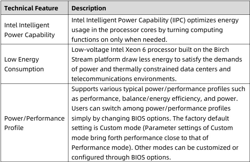
<td> Intel Intelligent Power Capability </td>
<td> Intel Intelligent Power Capability (IIPC) optimizes energy usage in the processor cores by turning computing functions on only when needed. </td>
</tr>
<tr>
<td> Low Energy Consumption </td>
<td> Low-voltage Intel Xeon 6 processor built on the Birch Stream platform draw less energy to satisfy the demands of power and thermally constrained data centers and telecommunications environments. </td>
</tr>
<tr>
<td> Power/Performance Profile </td>
<td> Supports various typical power/performance profiles such as performance, balance/energy efficiency, and power. Users can switch among power/performance profiles simply by changing BIOS options. The factory default setting is Custom mode (Parameter settings of Custom mode bring forth performance close to that of Performance mode). Other modes can be customized or configured through BIOS options. </td>
</tr>
</tbody>
</table>

<details style="margin: 0.3rem 0 1rem; padding: 0.4rem 0.6rem; background: rgba(255,255,255,0.03); border-radius: 4px; border: 1px solid rgba(255,255,255,0.08);">
  <summary style="cursor: pointer; font-size: 0.75rem; color: rgba(255,255,255,0.55);">📷 view source screenshot for verification (page 16)</summary>
  <img src="images/reducto/p016_table_0112.jpg" alt="table source p16" style="max-width: 100%; margin-top: 0.6rem; display: block;" />
</details>

7

<!-- page: 17 -->
White Paper for KAYTUS KR1180V3 Series Servers_Powered by Intel Processors

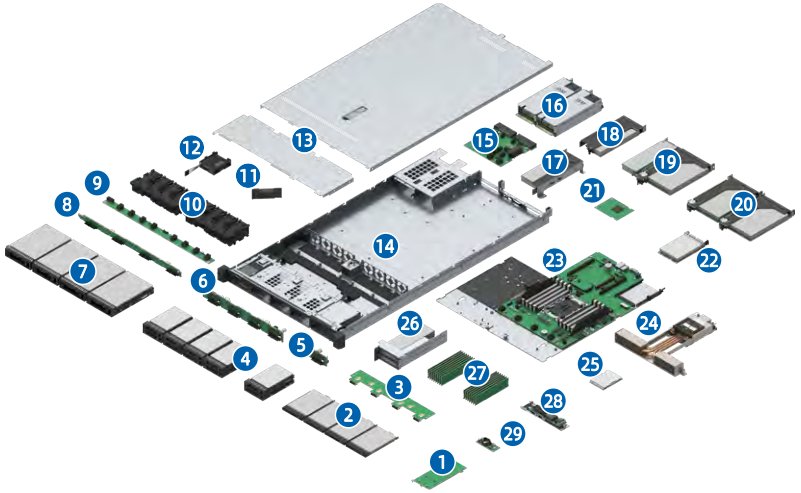
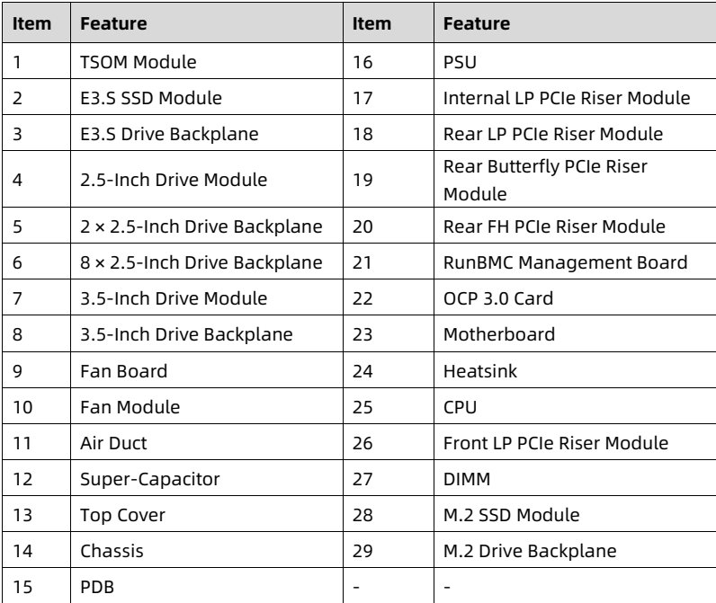
3 System Parts Breakdown

Figure 3-1 Exploded View

<figure style="margin: 1rem 0; padding: 0.6rem; background: rgba(255,255,255,0.04); border-radius: 4px;">
  <img src="images/reducto/p017_figure_0119.jpg" alt="figure p17" style="max-width: 100%; max-height: 480px; display: block; margin: 0 auto;" />
  <figcaption style="font-size: 0.78rem; color: rgba(255,255,255,0.55); text-align: center; margin-top: 0.5rem;">16
12 (15) 17 18 19

(10 20

22

26 24

28</figcaption>
</figure>

<table>
<thead>
<tr>
<th> Item </th>
<th> Feature </th>
<th> Item </th>
<th> Feature </th>
</tr>
</thead>
<tbody>
<tr>
<td> 1 </td>
<td> TSOM Module </td>
<td> 16 </td>
<td> PSU </td>
</tr>
<tr>
<td> 2 </td>
<td> E3.S SSD Module </td>
<td> 17 </td>
<td> Internal LP PCIe Riser Module </td>
</tr>
<tr>
<td> 3 </td>
<td> E3.S Drive Backplane </td>
<td> 18 </td>
<td> Rear LP PCIe Riser Module </td>
</tr>
<tr>
<td> 4 </td>
<td> 2.5-Inch Drive Module </td>
<td> 19 </td>
<td> Rear Butterfly PCIe Riser Module </td>
</tr>
<tr>
<td> 5 </td>
<td> 2 × 2.5-Inch Drive Backplane </td>
<td> 20 </td>
<td> Rear FH PCIe Riser Module </td>
</tr>
<tr>
<td> 6 </td>
<td> 8 × 2.5-Inch Drive Backplane </td>
<td> 21 </td>
<td> RunBMC Management Board </td>
</tr>
<tr>
<td> 7 </td>
<td> 3.5-Inch Drive Module </td>
<td> 22 </td>
<td> OCP 3.0 Card </td>
</tr>
<tr>
<td> 8 </td>
<td> 3.5-Inch Drive Backplane </td>
<td> 23 </td>
<td> Motherboard </td>
</tr>
<tr>
<td> 9 </td>
<td> Fan Board </td>
<td> 24 </td>
<td> Heatsink </td>
</tr>
<tr>
<td> 10 </td>
<td> Fan Module </td>
<td> 25 </td>
<td> CPU </td>
</tr>
<tr>
<td> 11 </td>
<td> Air Duct </td>
<td> 26 </td>
<td> Front LP PCIe Riser Module </td>
</tr>
<tr>
<td> 12 </td>
<td> Super-Capacitor </td>
<td> 27 </td>
<td> DIMM </td>
</tr>
<tr>
<td> 13 </td>
<td> Top Cover </td>
<td> 28 </td>
<td> M.2 SSD Module </td>
</tr>
<tr>
<td> 14 </td>
<td> Chassis </td>
<td> 29 </td>
<td> M.2 Drive Backplane </td>
</tr>
<tr>
<td> 15 </td>
<td> PDB </td>
<td> - </td>
<td> - </td>
</tr>
</tbody>
</table>

<details style="margin: 0.3rem 0 1rem; padding: 0.4rem 0.6rem; background: rgba(255,255,255,0.03); border-radius: 4px; border: 1px solid rgba(255,255,255,0.08);">
  <summary style="cursor: pointer; font-size: 0.75rem; color: rgba(255,255,255,0.55);">📷 view source screenshot for verification (page 17)</summary>
  <img src="images/reducto/p017_table_0120.jpg" alt="table source p17" style="max-width: 100%; margin-top: 0.6rem; display: block;" />
</details>

8

<!-- page: 18 -->
White Paper for KAYTUS KR1180V3 Series Servers_Powered by Intel Processors

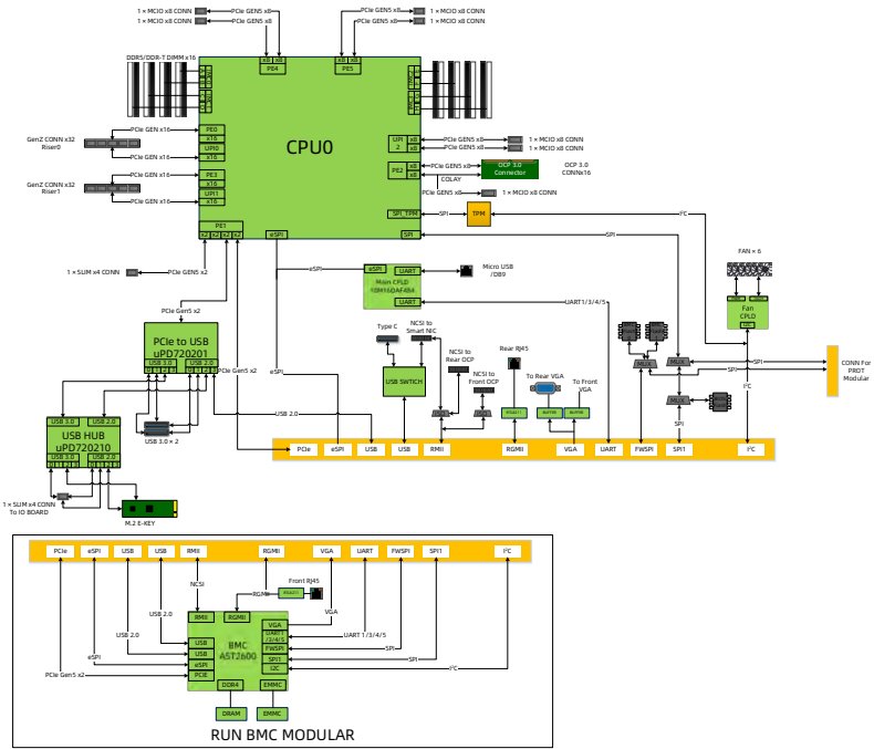
<b>4 System Logical Diagram</b>

Figure 4-1 System Logical Diagram

<figure style="margin: 1rem 0; padding: 0.6rem; background: rgba(255,255,255,0.04); border-radius: 4px;">
  <img src="images/reducto/p018_figure_0127.jpg" alt="figure p18" style="max-width: 100%; max-height: 480px; display: block; margin: 0 auto;" />
  <figcaption style="font-size: 0.78rem; color: rgba(255,255,255,0.55); text-align: center; margin-top: 0.5rem;">1x MCIO XCONN OGENS GENS 1xMCIO CONN
1 x MCIO XCONN GENS x PC GENS x1xMCO CONN

GenZ CONNx32 1x MCIOXCONN
Riser CPUO 1MCIO CONN

OCP 3.0 OCP 3.0
Connector CONN16
GenZ CONNx32
PCM GENS x 1x MC0xB CONN
_ ENG
DI TEN

Micro USB
1xSUM x4 CONN PO GENS x2
Main CPLD
DAFAM

PC Gen
Type C NCSI to

PCle to USB
Rear Rj45
UPD720201

SSWITCH NCSI to To Rear VGA to From Modular

USB HUB
USB 3.0 x 2
UPD720210 RGMI VGA UART FWSP SP PC

TO IO BOARD

RGMI VGA UART WSPI SPIT PC

Front RJ45

RGMI

UART 1/3/4/5
BMC

RUN BMC MODULAR</figcaption>
</figure>

• One Intel Xeon 6 processor built on the Birch Stream platform.

• Up to 16 DDR5 DIMMs.

• Up to 2 front PCIe 4.0 expansion slots, 3 rear PCIe 5.0 expansion slots and one rear OCP 3.0 card.

• The RAID card is connected to the CPU via the PCIe bus, and to the drive backplanes via SAS signal cables. Multiple local storage specifications are supported through different drive backplanes.

• The motherboard uses controllers to support 3 USB 3.0 ports, 1 USB 2.0/LCD port, 2 PCIe/SATA M.2 SSD connectors and 1 TF card connector.

• The RunBMC management board integrates an AST2600 management chip, and supports 1 VGA port, 1 BMC management network port, and other connectors.

9

<!-- page: 19 -->
White Paper for KAYTUS KR1180V3 Series Servers_Powered by Intel Processors

<b>5 Hardware Description</b>

<b>5.1 Front Panel</b>

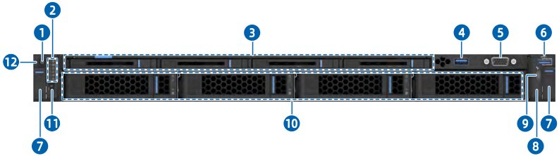
<b>5.1.1 4 × 3.5-Inch Drive + 4 × E3.S Drive Configuration</b>

IMPORTANT
A 3.5-inch drive tray can accommodate a 2.5-inch drive.

Figure 5-1 Front View

<figure style="margin: 1rem 0; padding: 0.6rem; background: rgba(255,255,255,0.04); border-radius: 4px;">
  <img src="images/reducto/p019_figure_0143.jpg" alt="figure p19" style="max-width: 100%; max-height: 480px; display: block; margin: 0 auto;" />
  <figcaption style="font-size: 0.78rem; color: rgba(255,255,255,0.55); text-align: center; margin-top: 0.5rem;">6

12

11 10</figcaption>
</figure>

<table>
<thead>
<tr>
<th> Item </th>
<th> Feature </th>
<th> Item </th>
<th> Feature </th>
</tr>
</thead>
<tbody>
<tr>
<td> 1 </td>
<td> Power Button and LED </td>
<td> 7 </td>
<td> Ear Latch </td>
</tr>
<tr>
<td> 2 </td>
<td> LEDs </td>
<td> 8 </td>
<td> USB Type-C Status LED </td>
</tr>
<tr>
<td> 3 </td>
<td> E3.S Drive Bay </td>
<td> 9 </td>
<td> USB Type-C Port </td>
</tr>
<tr>
<td> 4 </td>
<td> USB 2.0/LCD Port </td>
<td> 10 </td>
<td> 3.5-Inch Drive Bay </td>
</tr>
<tr>
<td> 5 </td>
<td> VGA Port </td>
<td> 11 </td>
<td> UID/BMC RST Button and LED </td>
</tr>
<tr>
<td> 6 </td>
<td> USB 3.0 Port </td>
<td> 12 </td>
<td> System Load Status LED </td>
</tr>
</tbody>
</table>

<details style="margin: 0.3rem 0 1rem; padding: 0.4rem 0.6rem; background: rgba(255,255,255,0.03); border-radius: 4px; border: 1px solid rgba(255,255,255,0.08);">
  <summary style="cursor: pointer; font-size: 0.75rem; color: rgba(255,255,255,0.55);">📷 view source screenshot for verification (page 19)</summary>
  <img src="images/reducto/p019_table_0144.jpg" alt="table source p19" style="max-width: 100%; margin-top: 0.6rem; display: block;" />
</details>

10

<!-- page: 20 -->
White Paper for KAYTUS KR1180V3 Series Servers_Powered by Intel Processors

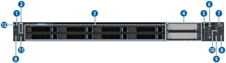
<b>5.1.2 8 × 2.5-Inch Drive + 2 × PCIe Slot Configuration</b>

Figure 5-2 Front View

<figure style="margin: 1rem 0; padding: 0.6rem; background: rgba(255,255,255,0.04); border-radius: 4px;">
  <img src="images/reducto/p020_figure_0151.jpg" alt="figure p20" style="max-width: 100%; max-height: 480px; display: block; margin: 0 auto;" />
  <figcaption style="font-size: 0.78rem; color: rgba(255,255,255,0.55); text-align: center; margin-top: 0.5rem;">12</figcaption>
</figure>

<table>
<thead>
<tr>
<th> Item </th>
<th> Feature </th>
<th> Item </th>
<th> Feature </th>
</tr>
</thead>
<tbody>
<tr>
<td> 1 </td>
<td> Power Button and LED </td>
<td> 7 </td>
<td> USB 3.0 Port </td>
</tr>
<tr>
<td> 2 </td>
<td> LEDs </td>
<td> 8 </td>
<td> Ear Latch </td>
</tr>
<tr>
<td> 3 </td>
<td> 2.5-Inch Drive Bay </td>
<td> 9 </td>
<td> USB Type-C Status LED </td>
</tr>
<tr>
<td> 4 </td>
<td> PCIe Riser Module </td>
<td> 10 </td>
<td> USB Type-C Port </td>
</tr>
<tr>
<td> 5 </td>
<td> USB 2.0/LCD Port </td>
<td> 11 </td>
<td> UID/BMC RST Button and LED </td>
</tr>
<tr>
<td> 6 </td>
<td> VGA Port </td>
<td> 12 </td>
<td> System Load Status LED </td>
</tr>
</tbody>
</table>

<details style="margin: 0.3rem 0 1rem; padding: 0.4rem 0.6rem; background: rgba(255,255,255,0.03); border-radius: 4px; border: 1px solid rgba(255,255,255,0.08);">
  <summary style="cursor: pointer; font-size: 0.75rem; color: rgba(255,255,255,0.55);">📷 view source screenshot for verification (page 20)</summary>
  <img src="images/reducto/p020_table_0152.jpg" alt="table source p20" style="max-width: 100%; margin-top: 0.6rem; display: block;" />
</details>

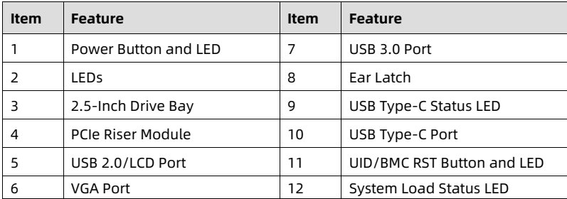
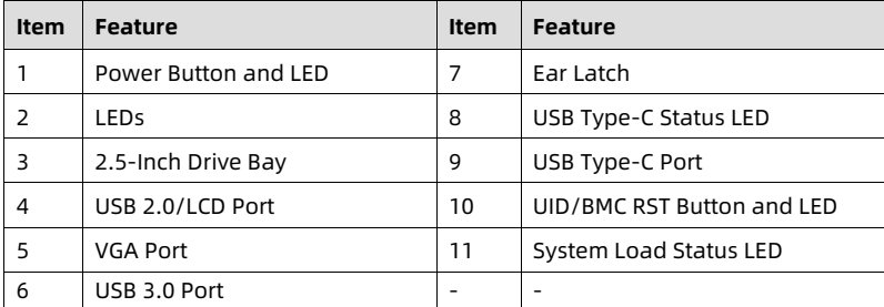
<b>5.1.3 10 × 2.5-Inch Drive Configuration</b>

Figure 5-3 Front View

<figure style="margin: 1rem 0; padding: 0.6rem; background: rgba(255,255,255,0.04); border-radius: 4px;">
  <img src="images/reducto/p020_figure_0155.jpg" alt="figure p20" style="max-width: 100%; max-height: 480px; display: block; margin: 0 auto;" />
  <figcaption style="font-size: 0.78rem; color: rgba(255,255,255,0.55); text-align: center; margin-top: 0.5rem;">10</figcaption>
</figure>

<table>
<thead>
<tr>
<th> Item </th>
<th> Feature </th>
<th> Item </th>
<th> Feature </th>
</tr>
</thead>
<tbody>
<tr>
<td> 1 </td>
<td> Power Button and LED </td>
<td> 7 </td>
<td> Ear Latch </td>
</tr>
<tr>
<td> 2 </td>
<td> LEDs </td>
<td> 8 </td>
<td> USB Type-C Status LED </td>
</tr>
<tr>
<td> 3 </td>
<td> 2.5-Inch Drive Bay </td>
<td> 9 </td>
<td> USB Type-C Port </td>
</tr>
<tr>
<td> 4 </td>
<td> USB 2.0/LCD Port </td>
<td> 10 </td>
<td> UID/BMC RST Button and LED </td>
</tr>
<tr>
<td> 5 </td>
<td> VGA Port </td>
<td> 11 </td>
<td> System Load Status LED </td>
</tr>
<tr>
<td> 6 </td>
<td> USB 3.0 Port </td>
<td> - </td>
<td> - </td>
</tr>
</tbody>
</table>

<details style="margin: 0.3rem 0 1rem; padding: 0.4rem 0.6rem; background: rgba(255,255,255,0.03); border-radius: 4px; border: 1px solid rgba(255,255,255,0.08);">
  <summary style="cursor: pointer; font-size: 0.75rem; color: rgba(255,255,255,0.55);">📷 view source screenshot for verification (page 20)</summary>
  <img src="images/reducto/p020_table_0156.jpg" alt="table source p20" style="max-width: 100%; margin-top: 0.6rem; display: block;" />
</details>

11

<!-- page: 21 -->
White Paper for KAYTUS KR1180V3 Series Servers_Powered by Intel Processors

<b>5.2 Rear Panel</b>

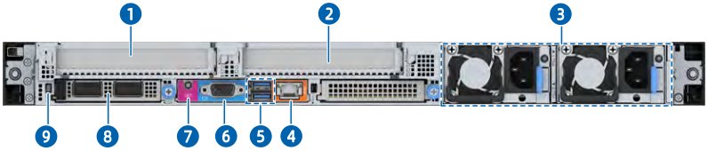
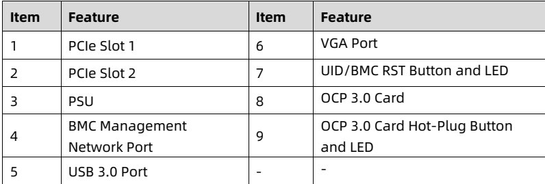
<b>5.2.1 2 × PCIe Slot Configuration</b>

Figure 5-4 Rear View

<figure style="margin: 1rem 0; padding: 0.6rem; background: rgba(255,255,255,0.04); border-radius: 4px;">
  <img src="images/reducto/p021_figure_0164.jpg" alt="figure p21" style="max-width: 100%; max-height: 480px; display: block; margin: 0 auto;" />
  <figcaption style="font-size: 0.78rem; color: rgba(255,255,255,0.55); text-align: center; margin-top: 0.5rem;">9 8</figcaption>
</figure>

<table>
<thead>
<tr>
<th> Item </th>
<th> Feature </th>
<th> Item </th>
<th> Feature </th>
</tr>
</thead>
<tbody>
<tr>
<td> 1 </td>
<td> PCIe Slot 1 </td>
<td> 6 </td>
<td> VGA Port </td>
</tr>
<tr>
<td> 2 </td>
<td> PCIe Slot 2 </td>
<td> 7 </td>
<td> UID/BMC RST Button and LED </td>
</tr>
<tr>
<td> 3 </td>
<td> PSU </td>
<td> 8 </td>
<td> OCP 3.0 Card </td>
</tr>
<tr>
<td> 4 </td>
<td> BMC Management Network Port </td>
<td> 9 </td>
<td> OCP 3.0 Card Hot-Plug Button and LED </td>
</tr>
<tr>
<td> 5 </td>
<td> USB 3.0 Port </td>
<td> - </td>
<td> - </td>
</tr>
</tbody>
</table>

<details style="margin: 0.3rem 0 1rem; padding: 0.4rem 0.6rem; background: rgba(255,255,255,0.03); border-radius: 4px; border: 1px solid rgba(255,255,255,0.08);">
  <summary style="cursor: pointer; font-size: 0.75rem; color: rgba(255,255,255,0.55);">📷 view source screenshot for verification (page 21)</summary>
  <img src="images/reducto/p021_table_0165.jpg" alt="table source p21" style="max-width: 100%; margin-top: 0.6rem; display: block;" />
</details>

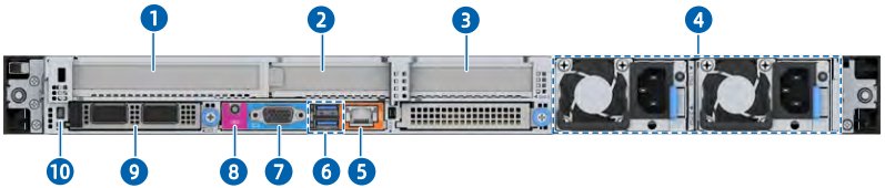
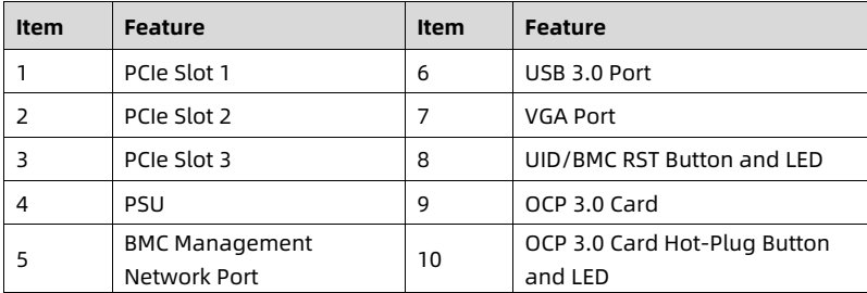
<b>5.2.2 3 × PCIe Slot Configuration</b>

Figure 5-5 Rear View

<figure style="margin: 1rem 0; padding: 0.6rem; background: rgba(255,255,255,0.04); border-radius: 4px;">
  <img src="images/reducto/p021_figure_0168.jpg" alt="figure p21" style="max-width: 100%; max-height: 480px; display: block; margin: 0 auto;" />
  <figcaption style="font-size: 0.78rem; color: rgba(255,255,255,0.55); text-align: center; margin-top: 0.5rem;">10 9 8</figcaption>
</figure>

<table>
<thead>
<tr>
<th> Item </th>
<th> Feature </th>
<th> Item </th>
<th> Feature </th>
</tr>
</thead>
<tbody>
<tr>
<td> 1 </td>
<td> PCIe Slot 1 </td>
<td> 6 </td>
<td> USB 3.0 Port </td>
</tr>
<tr>
<td> 2 </td>
<td> PCIe Slot 2 </td>
<td> 7 </td>
<td> VGA Port </td>
</tr>
<tr>
<td> 3 </td>
<td> PCIe Slot 3 </td>
<td> 8 </td>
<td> UID/BMC RST Button and LED </td>
</tr>
<tr>
<td> 4 </td>
<td> PSU </td>
<td> 9 </td>
<td> OCP 3.0 Card </td>
</tr>
<tr>
<td> 5 </td>
<td> BMC Management Network Port </td>
<td> 10 </td>
<td> OCP 3.0 Card Hot-Plug Button and LED </td>
</tr>
</tbody>
</table>

<details style="margin: 0.3rem 0 1rem; padding: 0.4rem 0.6rem; background: rgba(255,255,255,0.03); border-radius: 4px; border: 1px solid rgba(255,255,255,0.08);">
  <summary style="cursor: pointer; font-size: 0.75rem; color: rgba(255,255,255,0.55);">📷 view source screenshot for verification (page 21)</summary>
  <img src="images/reducto/p021_table_0169.jpg" alt="table source p21" style="max-width: 100%; margin-top: 0.6rem; display: block;" />
</details>

12

<!-- page: 22 -->
White Paper for KAYTUS KR1180V3 Series Servers_Powered by Intel Processors

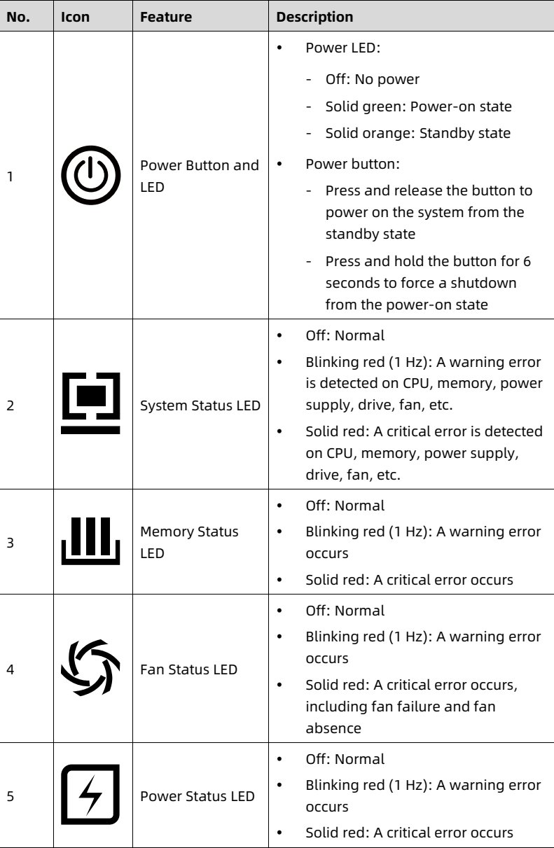
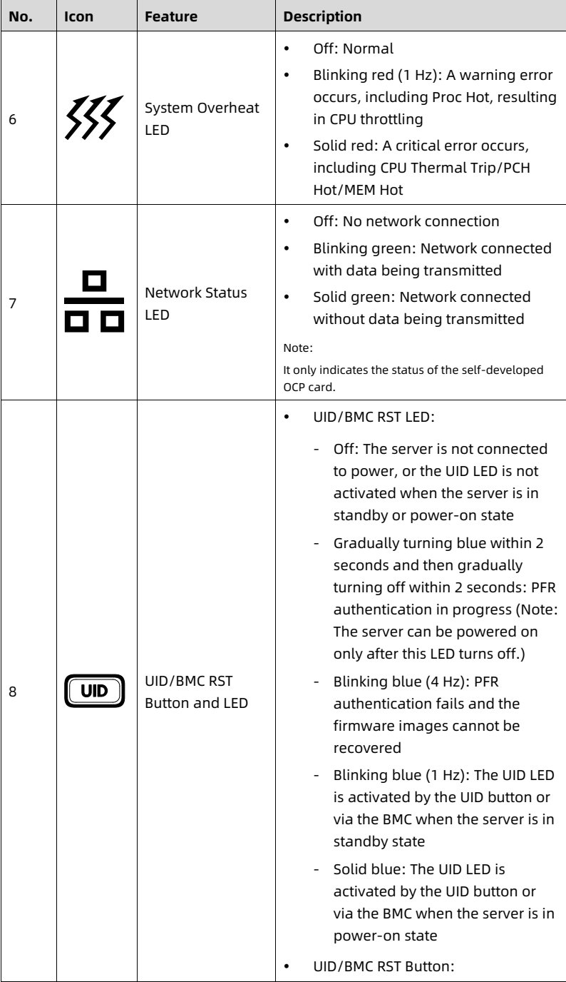
<b>5.3 LEDs and Buttons</b>

Table 5-1 LED and Button Description

<table>
<thead>
<tr>
<th> No. </th>
<th> Icon </th>
<th> Feature </th>
<th> Description </th>
</tr>
</thead>
<tbody>
<tr>
<td> 1 </td>
<td> [power-button] </td>
<td> Power Button and LED </td>
<td> • Power LED:
- Off: No power
- Solid green: Power-on state
- Solid orange: Standby state
• Power button:
- Press and release the button to power on the system from the standby state
- Press and hold the button for 6 seconds to force a shutdown from the power-on state </td>
</tr>
<tr>
<td> 2 </td>
<td> [system-status] </td>
<td> System Status LED </td>
<td> • Off: Normal
• Blinking red (1 Hz): A warning error is detected on CPU, memory, power supply, drive, fan, etc.
• Solid red: A critical error is detected on CPU, memory, power supply, drive, fan, etc. </td>
</tr>
<tr>
<td> 3 </td>
<td> [memory-status] </td>
<td> Memory Status LED </td>
<td> • Off: Normal
• Blinking red (1 Hz): A warning error occurs
• Solid red: A critical error occurs </td>
</tr>
<tr>
<td> 4 </td>
<td> [fan-status] </td>
<td> Fan Status LED </td>
<td> • Off: Normal
• Blinking red (1 Hz): A warning error occurs
• Solid red: A critical error occurs, including fan failure and fan absence </td>
</tr>
<tr>
<td> 5 </td>
<td> [power-status] </td>
<td> Power Status LED </td>
<td> • Off: Normal
• Blinking red (1 Hz): A warning error occurs
• Solid red: A critical error occurs </td>
</tr>
</tbody>
</table>

<details style="margin: 0.3rem 0 1rem; padding: 0.4rem 0.6rem; background: rgba(255,255,255,0.03); border-radius: 4px; border: 1px solid rgba(255,255,255,0.08);">
  <summary style="cursor: pointer; font-size: 0.75rem; color: rgba(255,255,255,0.55);">📷 view source screenshot for verification (page 22)</summary>
  <img src="images/reducto/p022_table_0176.jpg" alt="table source p22" style="max-width: 100%; margin-top: 0.6rem; display: block;" />
</details>

13

<!-- page: 23 -->
White Paper for KAYTUS KR1180V3 Series Servers_Powered by Intel Processors

<table>
<thead>
<tr>
<th> No. </th>
<th> Icon </th>
<th> Feature </th>
<th> Description </th>
</tr>
</thead>
<tbody>
<tr>
<td> 6 </td>
<td> [symbol] </td>
<td> System Overheat LED </td>
<td> • Off: Normal
• Blinking red (1 Hz): A warning error occurs, including Proc Hot, resulting in CPU throttling
• Solid red: A critical error occurs, including CPU Thermal Trip/PCH Hot/MEM Hot </td>
</tr>
<tr>
<td> 7 </td>
<td> [symbol] </td>
<td> Network Status LED </td>
<td> • Off: No network connection
• Blinking green: Network connected with data being transmitted
• Solid green: Network connected without data being transmitted
Note:
It only indicates the status of the self-developed OCP card. </td>
</tr>
<tr>
<td> 8 </td>
<td> [symbol] </td>
<td> UID/BMC RST Button and LED </td>
<td> • UID/BMC RST LED:
- Off: The server is not connected to power, or the UID LED is not activated when the server is in standby or power-on state
- Gradually turning blue within 2 seconds and then gradually turning off within 2 seconds: PFR authentication in progress (Note: The server can be powered on only after this LED turns off.)
- Blinking blue (4 Hz): PFR authentication fails and the firmware images cannot be recovered
- Blinking blue (1 Hz): The UID LED is activated by the UID button or via the BMC when the server is in standby state
- Solid blue: The UID LED is activated by the UID button or via the BMC when the server is in power-on state
• UID/BMC RST Button: </td>
</tr>
</tbody>
</table>

<details style="margin: 0.3rem 0 1rem; padding: 0.4rem 0.6rem; background: rgba(255,255,255,0.03); border-radius: 4px; border: 1px solid rgba(255,255,255,0.08);">
  <summary style="cursor: pointer; font-size: 0.75rem; color: rgba(255,255,255,0.55);">📷 view source screenshot for verification (page 23)</summary>
  <img src="images/reducto/p023_table_0181.jpg" alt="table source p23" style="max-width: 100%; margin-top: 0.6rem; display: block;" />
</details>

14

<!-- page: 24 -->
White Paper for KAYTUS KR1180V3 Series Servers_Powered by Intel Processors

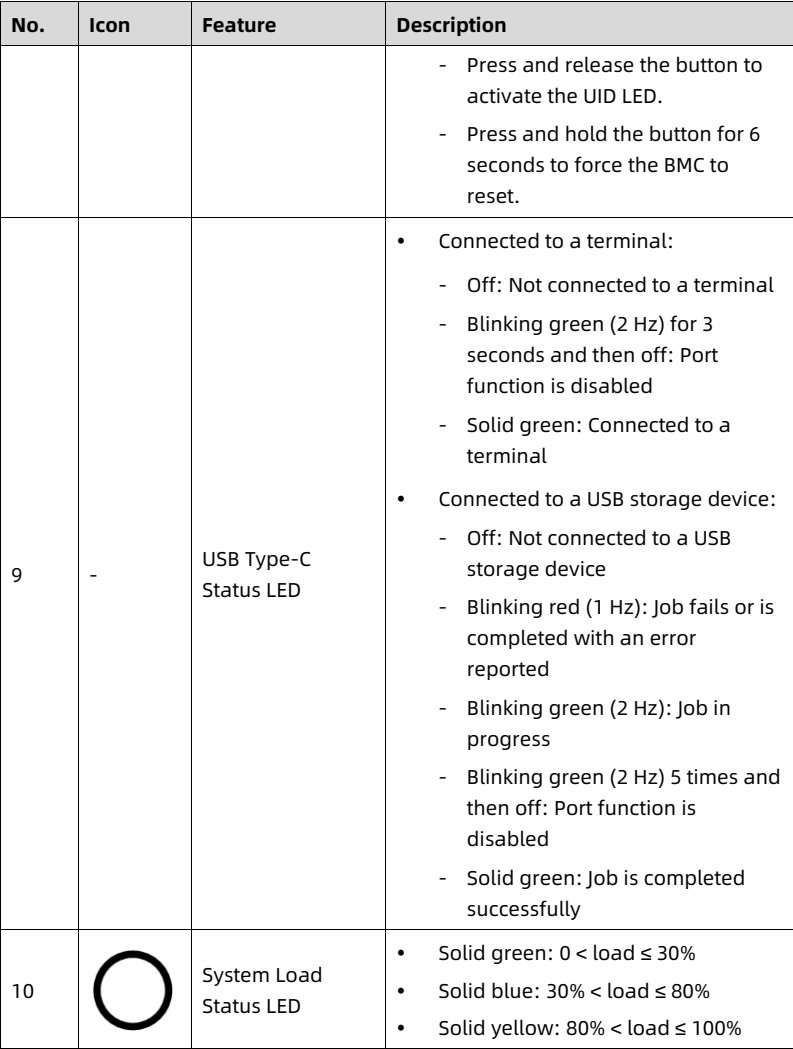
<table>
<thead>
<tr>
<th> No. </th>
<th> Icon </th>
<th> Feature </th>
<th> Description </th>
</tr>
</thead>
<tbody>
<tr>
<td></td>
<td></td>
<td></td>
<td> - Press and release the button to activate the UID LED.
- Press and hold the button for 6 seconds to force the BMC to reset. </td>
</tr>
<tr>
<td> 9 </td>
<td> - </td>
<td> USB Type-C Status LED </td>
<td> • Connected to a terminal:
- Off: Not connected to a terminal
- Blinking green (2 Hz) for 3 seconds and then off: Port function is disabled
- Solid green: Connected to a terminal
• Connected to a USB storage device:
- Off: Not connected to a USB storage device
- Blinking red (1 Hz): Job fails or is completed with an error reported
- Blinking green (2 Hz): Job in progress
- Blinking green (2 Hz) 5 times and then off: Port function is disabled
- Solid green: Job is completed successfully </td>
</tr>
<tr>
<td> 10 </td>
<td> ⦿ </td>
<td> System Load Status LED </td>
<td> • Solid green: 0 &lt; load ≤ 30%
• Solid blue: 30% &lt; load ≤ 80%
• Solid yellow: 80% &lt; load ≤ 100% </td>
</tr>
</tbody>
</table>

<details style="margin: 0.3rem 0 1rem; padding: 0.4rem 0.6rem; background: rgba(255,255,255,0.03); border-radius: 4px; border: 1px solid rgba(255,255,255,0.08);">
  <summary style="cursor: pointer; font-size: 0.75rem; color: rgba(255,255,255,0.55);">📷 view source screenshot for verification (page 24)</summary>
  <img src="images/reducto/p024_table_0186.jpg" alt="table source p24" style="max-width: 100%; margin-top: 0.6rem; display: block;" />
</details>

NOTE

• Warning error: Errors that result in redundancy degradation or loss, and other errors that have a minor impact on the system running and that require attention.

• Critical error: Errors that result in system crash/restart or part failure, and other errors that have a major impact on the system running and that require immediate action.

15

<!-- page: 25 -->
White Paper for KAYTUS KR1180V3 Series Servers_Powered by Intel Processors

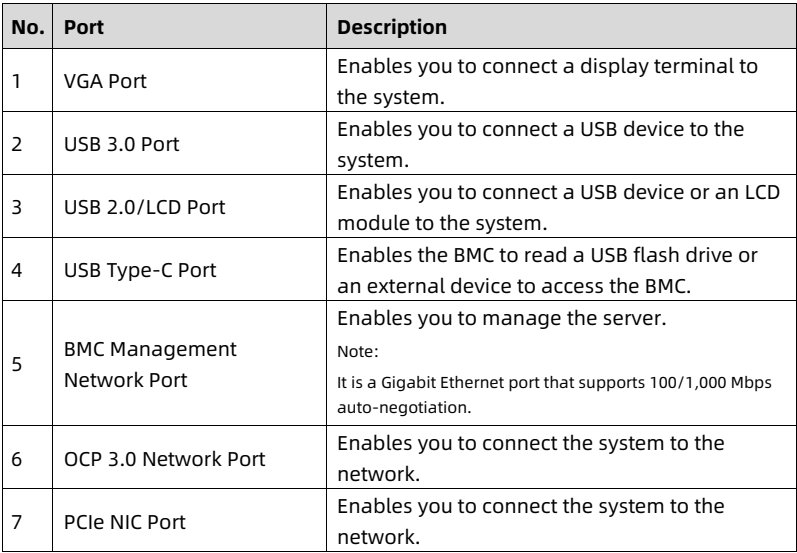
<b>5.4 Port Description</b>

Table 5-2 Port Description

<table>
<thead>
<tr>
<th> No. </th>
<th> Port </th>
<th> Description </th>
</tr>
</thead>
<tbody>
<tr>
<td> 1 </td>
<td> VGA Port </td>
<td> Enables you to connect a display terminal to the system. </td>
</tr>
<tr>
<td> 2 </td>
<td> USB 3.0 Port </td>
<td> Enables you to connect a USB device to the system. </td>
</tr>
<tr>
<td> 3 </td>
<td> USB 2.0/LCD Port </td>
<td> Enables you to connect a USB device or an LCD module to the system. </td>
</tr>
<tr>
<td> 4 </td>
<td> USB Type-C Port </td>
<td> Enables the BMC to read a USB flash drive or an external device to access the BMC. </td>
</tr>
<tr>
<td> 5 </td>
<td> BMC Management Network Port </td>
<td> Enables you to manage the server.
Note:
It is a Gigabit Ethernet port that supports 100/1,000 Mbps auto-negotiation. </td>
</tr>
<tr>
<td> 6 </td>
<td> OCP 3.0 Network Port </td>
<td> Enables you to connect the system to the network. </td>
</tr>
<tr>
<td> 7 </td>
<td> PCIe NIC Port </td>
<td> Enables you to connect the system to the network. </td>
</tr>
</tbody>
</table>

<details style="margin: 0.3rem 0 1rem; padding: 0.4rem 0.6rem; background: rgba(255,255,255,0.03); border-radius: 4px; border: 1px solid rgba(255,255,255,0.08);">
  <summary style="cursor: pointer; font-size: 0.75rem; color: rgba(255,255,255,0.55);">📷 view source screenshot for verification (page 25)</summary>
  <img src="images/reducto/p025_table_0196.jpg" alt="table source p25" style="max-width: 100%; margin-top: 0.6rem; display: block;" />
</details>

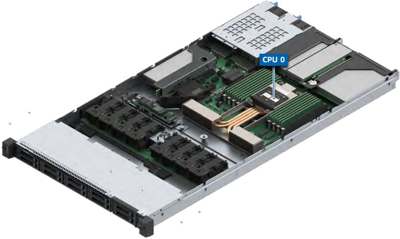
<b>5.5 Processor</b>

• Supports 1 processor.

• For specific processor options, consult your local sales representative or refer to <u>7.2 Hardware Compatibility</u>.

16

<!-- page: 26 -->
White Paper for KAYTUS KR1180V3 Series Servers_Powered by Intel Processors

Figure 5-6 Processor Location

<figure style="margin: 1rem 0; padding: 0.6rem; background: rgba(255,255,255,0.04); border-radius: 4px;">
  <img src="images/reducto/p026_figure_0205.jpg" alt="figure p26" style="max-width: 100%; max-height: 480px; display: block; margin: 0 auto;" />
  <figcaption style="font-size: 0.78rem; color: rgba(255,255,255,0.55); text-align: center; margin-top: 0.5rem;">CPU O</figcaption>
</figure>

<b>5.6 DDR5 DIMMs</b>

<b>5.6.1 Identification</b>

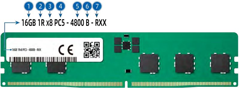
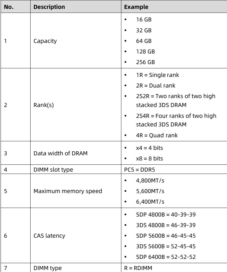
To determine DIMM characteristics, refer to the label attached to the DIMM and the following figure and table.

<figure style="margin: 1rem 0; padding: 0.6rem; background: rgba(255,255,255,0.04); border-radius: 4px;">
  <img src="images/reducto/p026_figure_0209.jpg" alt="figure p26" style="max-width: 100%; max-height: 480px; display: block; margin: 0 auto;" />
  <figcaption style="font-size: 0.78rem; color: rgba(255,255,255,0.55); text-align: center; margin-top: 0.5rem;">NOTE</figcaption>
</figure>

The following content is for illustrative purpose only. For supported DIMMs, refer to <u>7.2.2 DIMM Specifications</u>.

Figure 5-7 DIMM Identification

<figure style="margin: 1rem 0; padding: 0.6rem; background: rgba(255,255,255,0.04); border-radius: 4px;">
  <img src="images/reducto/p026_figure_0212.jpg" alt="figure p26" style="max-width: 100%; max-height: 480px; display: block; margin: 0 auto;" />
  <figcaption style="font-size: 0.78rem; color: rgba(255,255,255,0.55); text-align: center; margin-top: 0.5rem;">1 2 3 4 5 6 7

16GB 1R x8 PC5-4800 B - RXX

16GB 1Rx8 PCS-48008-RXX CE</figcaption>
</figure>

17

<!-- page: 27 -->
White Paper for KAYTUS KR1180V3 Series Servers_Powered by Intel Processors

<table>
<thead>
<tr>
<th> No. </th>
<th> Description </th>
<th> Example </th>
</tr>
</thead>
<tbody>
<tr>
<td> 1 </td>
<td> Capacity </td>
<td> • 16 GB
• 32 GB
• 64 GB
• 128 GB
• 256 GB </td>
</tr>
<tr>
<td> 2 </td>
<td> Rank(s) </td>
<td> • 1R = Single rank
• 2R = Dual rank
• 2S2R = Two ranks of two high stacked 3DS DRAM
• 2S4R = Four ranks of two high stacked 3DS DRAM
• 4R = Quad rank </td>
</tr>
<tr>
<td> 3 </td>
<td> Data width of DRAM </td>
<td> • x4 = 4 bits
• x8 = 8 bits </td>
</tr>
<tr>
<td> 4 </td>
<td> DIMM slot type </td>
<td> PC5 = DDR5 </td>
</tr>
<tr>
<td> 5 </td>
<td> Maximum memory speed </td>
<td> • 4,800MT/s
• 5,600MT/s
• 6,400MT/s </td>
</tr>
<tr>
<td> 6 </td>
<td> CAS latency </td>
<td> • SDP 4800B = 40-39-39
• 3DS 4800B = 46-39-39
• SDP 5600B = 46-45-45
• 3DS 5600B = 52-45-45
• SDP 6400B = 52-52-52 </td>
</tr>
<tr>
<td> 7 </td>
<td> DIMM type </td>
<td> R = RDIMM </td>
</tr>
</tbody>
</table>

<details style="margin: 0.3rem 0 1rem; padding: 0.4rem 0.6rem; background: rgba(255,255,255,0.03); border-radius: 4px; border: 1px solid rgba(255,255,255,0.08);">
  <summary style="cursor: pointer; font-size: 0.75rem; color: rgba(255,255,255,0.55);">📷 view source screenshot for verification (page 27)</summary>
  <img src="images/reducto/p027_table_0217.jpg" alt="table source p27" style="max-width: 100%; margin-top: 0.6rem; display: block;" />
</details>

<b>5.6.2 Memory Subsystem Architecture</b>

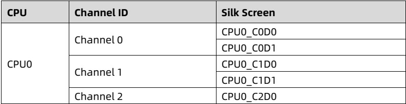
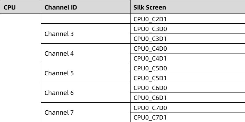
The server supports 16 DIMM slots and 8 memory channels per CPU.

Table 5-3 DIMM Slot List

<table>
<thead>
<tr>
<th> CPU </th>
<th> Channel ID </th>
<th> Silk Screen </th>
</tr>
</thead>
<tbody>
<tr>
<td rowspan="5"> CPU0 </td>
<td rowspan="2"> Channel 0 </td>
<td> CPU0_C0D0 </td>
</tr>
<tr>
<td> CPU0_C0D1 </td>
</tr>
<tr>
<td rowspan="2"> Channel 1 </td>
<td> CPU0_C1D0 </td>
</tr>
<tr>
<td> CPU0_C1D1 </td>
</tr>
<tr>
<td> Channel 2 </td>
<td> CPU0_C2D0 </td>
</tr>
</tbody>
</table>

<details style="margin: 0.3rem 0 1rem; padding: 0.4rem 0.6rem; background: rgba(255,255,255,0.03); border-radius: 4px; border: 1px solid rgba(255,255,255,0.08);">
  <summary style="cursor: pointer; font-size: 0.75rem; color: rgba(255,255,255,0.55);">📷 view source screenshot for verification (page 27)</summary>
  <img src="images/reducto/p027_table_0221.jpg" alt="table source p27" style="max-width: 100%; margin-top: 0.6rem; display: block;" />
</details>

18

<!-- page: 28 -->
White Paper for KAYTUS KR1180V3 Series Servers_Powered by Intel Processors

<table>
<thead>
<tr>
<th> CPU </th>
<th> Channel ID </th>
<th> Silk Screen </th>
</tr>
</thead>
<tbody>
<tr>
<td rowspan="12"></td>
<td></td>
<td> CPU0_C2D1 </td>
</tr>
<tr>
<td rowspan="2"> Channel 3 </td>
<td> CPU0_C3D0 </td>
</tr>
<tr>
<td> CPU0_C3D1 </td>
</tr>
<tr>
<td rowspan="2"> Channel 4 </td>
<td> CPU0_C4D0 </td>
</tr>
<tr>
<td> CPU0_C4D1 </td>
</tr>
<tr>
<td rowspan="2"> Channel 5 </td>
<td> CPU0_C5D0 </td>
</tr>
<tr>
<td> CPU0_C5D1 </td>
</tr>
<tr>
<td rowspan="2"> Channel 6 </td>
<td> CPU0_C6D0 </td>
</tr>
<tr>
<td> CPU0_C6D1 </td>
</tr>
<tr>
<td rowspan="2"> Channel 7 </td>
<td> CPU0_C7D0 </td>
</tr>
<tr>
<td> CPU0_C7D1 </td>
</tr>
</tbody>
</table>

<details style="margin: 0.3rem 0 1rem; padding: 0.4rem 0.6rem; background: rgba(255,255,255,0.03); border-radius: 4px; border: 1px solid rgba(255,255,255,0.08);">
  <summary style="cursor: pointer; font-size: 0.75rem; color: rgba(255,255,255,0.55);">📷 view source screenshot for verification (page 28)</summary>
  <img src="images/reducto/p028_table_0226.jpg" alt="table source p28" style="max-width: 100%; margin-top: 0.6rem; display: block;" />
</details>

<b>5.6.3 Compatibility</b>

Refer to the following rules to configure the DDR5 DIMMs.

) IMPORTANT

• A server must use DDR5 DIMMs with the same part number (P/N code). All DDR5 DIMMs operate at the same speed, which is the lowest of:

- Memory speed supported by a specific CPU.

- Maximum operating speed of a specific memory configuration.

• Mixing DDR5 DIMMs of different specifications (capacity, bit width, rank, height, etc.) is not supported.

• The maximum memory capacity supported is different for different CPU models.

• The maximum number of DIMMs supported varies by CPU type, DIMM type and rank quantity.

• For specific system component options, consult your local sales representative or refer to <u>7.2 Hardware Compatibility</u>.

NOTE

Maximum number of DIMMs supported per channel ≤ Maximum number of ranks supported per channel ÷ Number of ranks per DIMM.

19

<!-- page: 29 -->
White Paper for KAYTUS KR1180V3 Series Servers_Powered by Intel Processors

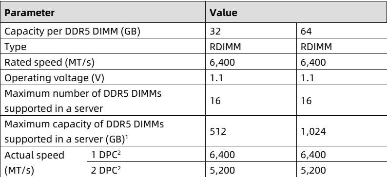
Table 5-4 DDR5 DIMM Specifications

<table>
<thead>
<tr>
<th colspan="2"> <b>Parameter</b> </th>
<th colspan="2"> <b>Value</b> </th>
</tr>
</thead>
<tbody>
<tr>
<td colspan="2"> Capacity per DDR5 DIMM (GB) </td>
<td> 32 </td>
<td> 64 </td>
</tr>
<tr>
<td colspan="2"> Type </td>
<td> RDIMM </td>
<td> RDIMM </td>
</tr>
<tr>
<td colspan="2"> Rated speed (MT/s) </td>
<td> 6,400 </td>
<td> 6,400 </td>
</tr>
<tr>
<td colspan="2"> Operating voltage (V) </td>
<td> 1.1 </td>
<td> 1.1 </td>
</tr>
<tr>
<td colspan="2"> Maximum number of DDR5 DIMMs supported in a server </td>
<td> 16 </td>
<td> 16 </td>
</tr>
<tr>
<td colspan="2"> Maximum capacity of DDR5 DIMMs supported in a server (GB)<sup>1</sup> </td>
<td> 512 </td>
<td> 1,024 </td>
</tr>
<tr>
<td rowspan="2"> Actual speed (MT/s) </td>
<td> 1 DPC<sup>2</sup> </td>
<td> 6,400 </td>
<td> 6,400 </td>
</tr>
<tr>
<td> 2 DPC<sup>2</sup> </td>
<td> 5,200 </td>
<td> 5,200 </td>
</tr>
</tbody>
</table>

<details style="margin: 0.3rem 0 1rem; padding: 0.4rem 0.6rem; background: rgba(255,255,255,0.03); border-radius: 4px; border: 1px solid rgba(255,255,255,0.08);">
  <summary style="cursor: pointer; font-size: 0.75rem; color: rgba(255,255,255,0.55);">📷 view source screenshot for verification (page 29)</summary>
  <img src="images/reducto/p029_table_0244.jpg" alt="table source p29" style="max-width: 100%; margin-top: 0.6rem; display: block;" />
</details>

Notes:

1. It indicates the maximum memory capacity supported when all the DIMM slots are populated with DDR5 DIMMs. The maximum DDR5 capacity varies by CPU type.

2. DIMM Per Channel (DPC) is the number of DIMMs per memory channel.

- The information above is for reference only. Consult your local sales representative for details.

<b>5.6.4 DIMM Population Rules</b>

General population rules for DDR5 DIMMs:

• Install DIMMs only when the corresponding processor is installed.

• Install dummies in the empty DIMM slots.

Population rules for DDR5 DIMMs in specific modes:

• Memory sparing mode

- Follow the general population rules.

- Each channel must have a valid online spare configuration.

- Each channel can have a different online spare configuration.

- Each channel with a DIMM installed must have a spare rank.

• Memory mirroring mode

- Follow the general population rules.

- Each processor supports 8 integrated memory controllers (iMCs). Each iMC has 2 channels to be populated with DIMMs. Installed DIMMs must be of the same capacity and organization.

20

<!-- page: 30 -->
White Paper for KAYTUS KR1180V3 Series Servers_Powered by Intel Processors

<b>5.6.5 DIMM Slot Layout</b>

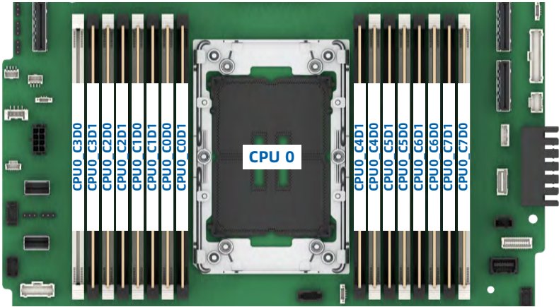
Up to 16 DDR5 DIMMs can be installed in a server, and a balanced DIMM configuration is recommended for optimal memory performance. DIMM configuration must be compliant with the DIMM population rules.

Figure 5-8 DIMM Slot Layout

<figure style="margin: 1rem 0; padding: 0.6rem; background: rgba(255,255,255,0.04); border-radius: 4px;">
  <img src="images/reducto/p030_figure_0269.jpg" alt="figure p30" style="max-width: 100%; max-height: 480px; display: block; margin: 0 auto;" />
  <figcaption style="font-size: 0.78rem; color: rgba(255,255,255,0.55); text-align: center; margin-top: 0.5rem;">GOD GOO CPU0_C3D0 CPU0_C3D1 CPUO_C2D0 CPU0_C2D1 EPUO_C1DO CPUO CIDI CPUO_CODO CPU0_COD1 CPU O CPUO C4D1 PUO_C5D1 CPU0_C5D0 CPU0_C6D1 CPUO C6DO CPU0_C7D1 CPU0_C7DO E www</figcaption>
</figure>

Table 5-5 DDR5 DIMM Population Rules for 6700E-Series CPU Configuration

<table>
<thead>
<tr>
<th rowspan="2"> DDR QTY </th>
<th colspan="16"> CPU0 </th>
</tr>
<tr>
<th> C0D0 </th>
<th> C0D1 </th>
<th> C1D0 </th>
<th> C1D1 </th>
<th> C2D0 </th>
<th> C2D1 </th>
<th> C3D0 </th>
<th> C3D1 </th>
<th> C4D0 </th>
<th> C4D1 </th>
<th> C5D0 </th>
<th> C5D1 </th>
<th> C6D0 </th>
<th> C6D1 </th>
<th> C7D0 </th>
<th> C7D1 </th>
</tr>
</thead>
<tbody>
<tr>
<td> 1 </td>
<td> ● </td>
<td></td>
<td></td>
<td></td>
<td></td>
<td></td>
<td></td>
<td></td>
<td></td>
<td></td>
<td></td>
<td></td>
<td></td>
<td></td>
<td></td>
<td></td>
</tr>
<tr>
<td> 4 </td>
<td> ● </td>
<td></td>
<td></td>
<td></td>
<td> ● </td>
<td></td>
<td></td>
<td></td>
<td> ● </td>
<td></td>
<td></td>
<td></td>
<td> ● </td>
<td></td>
<td></td>
<td></td>
</tr>
<tr>
<td> 8 </td>
<td> ● </td>
<td></td>
<td> ● </td>
<td></td>
<td> ● </td>
<td></td>
<td> ● </td>
<td></td>
<td> ● </td>
<td></td>
<td> ● </td>
<td></td>
<td> ● </td>
<td></td>
<td> ● </td>
<td></td>
</tr>
<tr>
<td> 16 </td>
<td> ● </td>
<td> ● </td>
<td> ● </td>
<td> ● </td>
<td> ● </td>
<td> ● </td>
<td> ● </td>
<td> ● </td>
<td> ● </td>
<td> ● </td>
<td> ● </td>
<td> ● </td>
<td> ● </td>
<td> ● </td>
<td> ● </td>
<td> ● </td>
</tr>
</tbody>
</table>

<details style="margin: 0.3rem 0 1rem; padding: 0.4rem 0.6rem; background: rgba(255,255,255,0.03); border-radius: 4px; border: 1px solid rgba(255,255,255,0.08);">
  <summary style="cursor: pointer; font-size: 0.75rem; color: rgba(255,255,255,0.55);">📷 view source screenshot for verification (page 30)</summary>
  <img src="images/reducto/p030_table_0271.jpg" alt="table source p30" style="max-width: 100%; margin-top: 0.6rem; display: block;" />
</details>

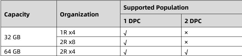
Table 5-6 Population Requirements for 6700E-Series CPU Configuration

<table>
<thead>
<tr>
<th rowspan="2"> Capacity </th>
<th rowspan="2"> Organization </th>
<th colspan="2"> Supported Population </th>
</tr>
<tr>
<th> 1 DPC </th>
<th> 2 DPC </th>
</tr>
</thead>
<tbody>
<tr>
<td rowspan="2"> 32 GB </td>
<td> 1R x4 </td>
<td> ✓ </td>
<td> ✕ </td>
</tr>
<tr>
<td> 2R x8 </td>
<td> ✓ </td>
<td> ✕ </td>
</tr>
<tr>
<td> 64 GB </td>
<td> 2R x4 </td>
<td> ✓ </td>
<td> ✓ </td>
</tr>
</tbody>
</table>

<details style="margin: 0.3rem 0 1rem; padding: 0.4rem 0.6rem; background: rgba(255,255,255,0.03); border-radius: 4px; border: 1px solid rgba(255,255,255,0.08);">
  <summary style="cursor: pointer; font-size: 0.75rem; color: rgba(255,255,255,0.55);">📷 view source screenshot for verification (page 30)</summary>
  <img src="images/reducto/p030_table_0273.jpg" alt="table source p30" style="max-width: 100%; margin-top: 0.6rem; display: block;" />
</details>

21

<!-- page: 31 -->
White Paper for KAYTUS KR1180V3 Series Servers_Powered by Intel Processors

<b>5.7 Storage</b>

<figure style="margin: 1rem 0; padding: 0.6rem; background: rgba(255,255,255,0.04); border-radius: 4px;">
  <img src="images/reducto/p031_figure_0279.jpg" alt="figure p31" style="max-width: 100%; max-height: 480px; display: block; margin: 0 auto;" />
  <figcaption style="font-size: 0.78rem; color: rgba(255,255,255,0.55); text-align: center; margin-top: 0.5rem;">CAUTION</figcaption>
</figure>

Mixing of storage controllers may result in drive letter drift under the OS.

<b>5.7.1 Drive Configurations</b>

NOTE

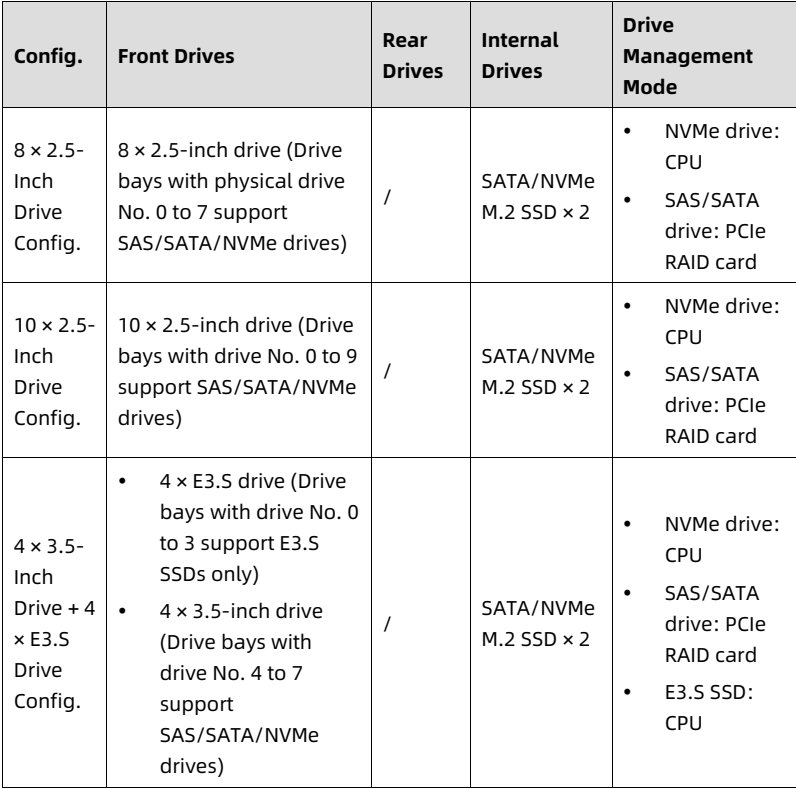
For the physical drive No. of each configuration, refer to <u>5.7.2 Drive Numbering.</u>

Table 5-7 Drive Configurations

<table>
<thead>
<tr>
<th> Config. </th>
<th> Front Drives </th>
<th> Rear Drives </th>
<th> Internal Drives </th>
<th> Drive Management Mode </th>
</tr>
</thead>
<tbody>
<tr>
<td> 8 × 2.5-Inch Drive Config. </td>
<td> 8 × 2.5-inch drive (Drive bays with physical drive No. 0 to 7 support SAS/SATA/NVMe drives) </td>
<td> / </td>
<td> SATA/NVMe M.2 SSD × 2 </td>
<td> • NVMe drive: CPU
• SAS/SATA drive: PCIe RAID card </td>
</tr>
<tr>
<td> 10 × 2.5-Inch Drive Config. </td>
<td> 10 × 2.5-inch drive (Drive bays with drive No. 0 to 9 support SAS/SATA/NVMe drives) </td>
<td> / </td>
<td> SATA/NVMe M.2 SSD × 2 </td>
<td> • NVMe drive: CPU
• SAS/SATA drive: PCIe RAID card </td>
</tr>
<tr>
<td> 4 × 3.5-Inch Drive + 4 × E3.S Drive Config. </td>
<td> • 4 × E3.S drive (Drive bays with drive No. 0 to 3 support E3.S SSDs only)
• 4 × 3.5-inch drive (Drive bays with drive No. 4 to 7 support SAS/SATA/NVMe drives) </td>
<td> / </td>
<td> SATA/NVMe M.2 SSD × 2 </td>
<td> • NVMe drive: CPU
• SAS/SATA drive: PCIe RAID card
• E3.S SSD: CPU </td>
</tr>
</tbody>
</table>

<details style="margin: 0.3rem 0 1rem; padding: 0.4rem 0.6rem; background: rgba(255,255,255,0.03); border-radius: 4px; border: 1px solid rgba(255,255,255,0.08);">
  <summary style="cursor: pointer; font-size: 0.75rem; color: rgba(255,255,255,0.55);">📷 view source screenshot for verification (page 31)</summary>
  <img src="images/reducto/p031_table_0285.jpg" alt="table source p31" style="max-width: 100%; margin-top: 0.6rem; display: block;" />
</details>

22

<!-- page: 32 -->
White Paper for KAYTUS KR1180V3 Series Servers_Powered by Intel Processors

<b>5.7.2 Drive Numbering</b>

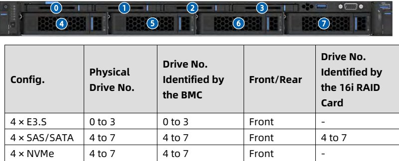
<b>1. 4 × 3.5-Inch Drive + 4 × E3.S Drive Configuration</b>

Figure 5-9 Drive Numbering

<table>
<thead>
<tr>
<th> Config. </th>
<th> Physical Drive No. </th>
<th> Drive No. Identified by the BMC </th>
<th> Front/Rear </th>
<th> Drive No. Identified by the 16i RAID Card </th>
</tr>
</thead>
<tbody>
<tr>
<td> 4 × E3.S </td>
<td> 0 to 3 </td>
<td> 0 to 3 </td>
<td> Front </td>
<td> - </td>
</tr>
<tr>
<td> 4 × SAS/SATA </td>
<td> 4 to 7 </td>
<td> 4 to 7 </td>
<td> Front </td>
<td> 4 to 7 </td>
</tr>
<tr>
<td> 4 × NVMe </td>
<td> 4 to 7 </td>
<td> 4 to 7 </td>
<td> Front </td>
<td> - </td>
</tr>
</tbody>
</table>

<details style="margin: 0.3rem 0 1rem; padding: 0.4rem 0.6rem; background: rgba(255,255,255,0.03); border-radius: 4px; border: 1px solid rgba(255,255,255,0.08);">
  <summary style="cursor: pointer; font-size: 0.75rem; color: rgba(255,255,255,0.55);">📷 view source screenshot for verification (page 32)</summary>
  <img src="images/reducto/p032_table_0293.jpg" alt="table source p32" style="max-width: 100%; margin-top: 0.6rem; display: block;" />
</details>

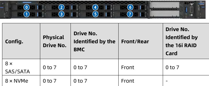
<b>2. 8 × 2.5-Inch SAS/SATA/NVMe Drive Configuration</b>

Figure 5-10 Drive Numbering

<table>
<thead>
<tr>
<th> <b>Config.</b> </th>
<th> <b>Physical Drive No.</b> </th>
<th> <b>Drive No. Identified by the BMC</b> </th>
<th> <b>Front/Rear</b> </th>
<th> <b>Drive No. Identified by the 16i RAID Card</b> </th>
</tr>
</thead>
<tbody>
<tr>
<td> 8 × SAS/SATA </td>
<td> 0 to 7 </td>
<td> 0 to 7 </td>
<td> Front </td>
<td> 0 to 7 </td>
</tr>
<tr>
<td> 8 × NVMe </td>
<td> 0 to 7 </td>
<td> 0 to 7 </td>
<td> Front </td>
<td> - </td>
</tr>
</tbody>
</table>

<details style="margin: 0.3rem 0 1rem; padding: 0.4rem 0.6rem; background: rgba(255,255,255,0.03); border-radius: 4px; border: 1px solid rgba(255,255,255,0.08);">
  <summary style="cursor: pointer; font-size: 0.75rem; color: rgba(255,255,255,0.55);">📷 view source screenshot for verification (page 32)</summary>
  <img src="images/reducto/p032_table_0296.jpg" alt="table source p32" style="max-width: 100%; margin-top: 0.6rem; display: block;" />
</details>

<b>3. 10 × 2.5-Inch SAS/SATA/NVMe Drive Configuration</b>

Figure 5-11 Drive Numbering

<figure style="margin: 1rem 0; padding: 0.6rem; background: rgba(255,255,255,0.04); border-radius: 4px;">
  <img src="images/reducto/p032_figure_0299.jpg" alt="figure p32" style="max-width: 100%; max-height: 480px; display: block; margin: 0 auto;" />
  <figcaption style="font-size: 0.78rem; color: rgba(255,255,255,0.55); text-align: center; margin-top: 0.5rem;">0 2)

(1 3 5 (7) 9</figcaption>
</figure>

23

<!-- page: 33 -->
White Paper for KAYTUS KR1180V3 Series Servers_Powered by Intel Processors

<table>
<thead>
<tr>
<th> Config. </th>
<th> Physical Drive No. </th>
<th> Drive No. Identified by the BMC </th>
<th> Front/Rear </th>
<th> Drive No. Identified by the 16i RAID Card </th>
</tr>
</thead>
<tbody>
<tr>
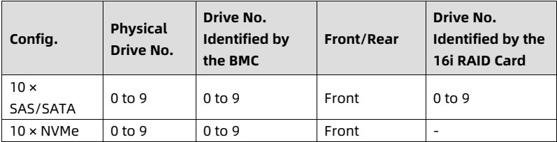
<td> 10 × SAS/SATA </td>
<td> 0 to 9 </td>
<td> 0 to 9 </td>
<td> Front </td>
<td> 0 to 9 </td>
</tr>
<tr>
<td> 10 × NVMe </td>
<td> 0 to 9 </td>
<td> 0 to 9 </td>
<td> Front </td>
<td> - </td>
</tr>
</tbody>
</table>

<details style="margin: 0.3rem 0 1rem; padding: 0.4rem 0.6rem; background: rgba(255,255,255,0.03); border-radius: 4px; border: 1px solid rgba(255,255,255,0.08);">
  <summary style="cursor: pointer; font-size: 0.75rem; color: rgba(255,255,255,0.55);">📷 view source screenshot for verification (page 33)</summary>
  <img src="images/reducto/p033_table_0304.jpg" alt="table source p33" style="max-width: 100%; margin-top: 0.6rem; display: block;" />
</details>

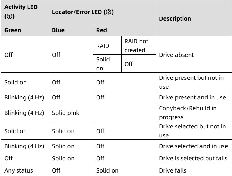
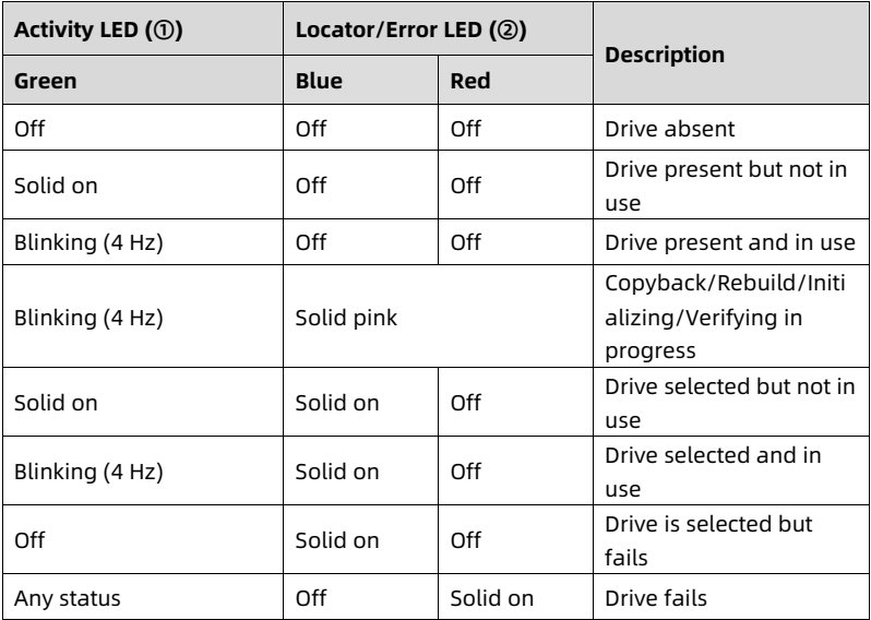
<b>5.7.3 Drive LEDs</b>

<b>1. SAS/SATA Drive LEDs</b>

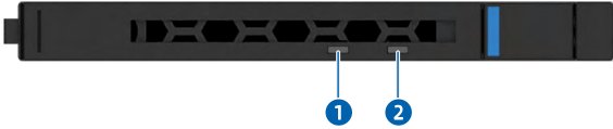
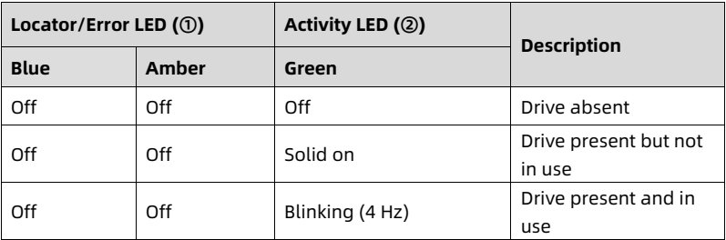
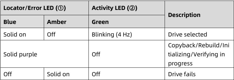
Figure 5-12 SAS/SATA Drive LEDs

![figure](images/reducto/p033_figure_0308.jpg)

<table>
<thead>
<tr>
<th> Activity LED (①) </th>
<th colspan="3"> Locator/Error LED (②) </th>
<th> Description </th>
</tr>
<tr>
<th> Green </th>
<th> Blue </th>
<th colspan="2"> Red </th>
<th></th>
</tr>
</thead>
<tbody>
<tr>
<td rowspan="2"> Off </td>
<td> RAID </td>
<td> RAID not created </td>
<td rowspan="2"> Drive absent </td>
</tr>
<tr>
<td> Solid on </td>
<td> Off </td>
</tr>
<tr>
<td> Solid on </td>
<td> Off </td>
<td colspan="2"> Off </td>
<td> Drive present but not in use </td>
</tr>
<tr>
<td> Blinking (4 Hz) </td>
<td> Off </td>
<td colspan="2"> Off </td>
<td> Drive present and in use </td>
</tr>
<tr>
<td> Blinking (4 Hz) </td>
<td colspan="3"> Solid pink </td>
<td> Copyback/Rebuild in progress </td>
</tr>
<tr>
<td> Solid on </td>
<td> Solid on </td>
<td colspan="2"> Off </td>
<td> Drive selected but not in use </td>
</tr>
<tr>
<td> Blinking (4 Hz) </td>
<td> Solid on </td>
<td colspan="2"> Off </td>
<td> Drive selected and in use </td>
</tr>
<tr>
<td> Off </td>
<td> Solid on </td>
<td colspan="2"> Off </td>
<td> Drive is selected but fails </td>
</tr>
<tr>
<td> Any status </td>
<td> Off </td>
<td colspan="2"> Solid on </td>
<td> Drive fails </td>
</tr>
</tbody>
</table>

<details style="margin: 0.3rem 0 1rem; padding: 0.4rem 0.6rem; background: rgba(255,255,255,0.03); border-radius: 4px; border: 1px solid rgba(255,255,255,0.08);">
  <summary style="cursor: pointer; font-size: 0.75rem; color: rgba(255,255,255,0.55);">📷 view source screenshot for verification (page 33)</summary>
  <img src="images/reducto/p033_table_0309.jpg" alt="table source p33" style="max-width: 100%; margin-top: 0.6rem; display: block;" />
</details>

24

<!-- page: 34 -->
White Paper for KAYTUS KR1180V3 Series Servers_Powered by Intel Processors

<b>2. NVMe Drive LEDs</b>

Figure 5-13 NVMe Drive LEDs

![figure](images/reducto/p034_figure_0316.jpg)

<table>
<thead>
<tr>
<th> <b>Activity LED (①)</b> </th>
<th colspan="2"> <b>Locator/Error LED (②)</b> </th>
<th> <b>Description</b> </th>
</tr>
<tr>
<th> <b>Green</b> </th>
<th> <b>Blue</b> </th>
<th> <b>Red</b> </th>
<th></th>
</tr>
</thead>
<tbody>
<tr>
<td> Off </td>
<td> Off </td>
<td> Off </td>
<td> Drive absent </td>
</tr>
<tr>
<td> Solid on </td>
<td> Off </td>
<td> Off </td>
<td> Drive present but not in use </td>
</tr>
<tr>
<td> Blinking (4 Hz) </td>
<td> Off </td>
<td> Off </td>
<td> Drive present and in use </td>
</tr>
<tr>
<td> Blinking (4 Hz) </td>
<td colspan="2"> Solid pink </td>
<td> Copyback/Rebuild/Initializing/Verifying in progress </td>
</tr>
<tr>
<td> Solid on </td>
<td> Solid on </td>
<td> Off </td>
<td> Drive selected but not in use </td>
</tr>
<tr>
<td> Blinking (4 Hz) </td>
<td> Solid on </td>
<td> Off </td>
<td> Drive selected and in use </td>
</tr>
<tr>
<td> Off </td>
<td> Solid on </td>
<td> Off </td>
<td> Drive is selected but fails </td>
</tr>
<tr>
<td> Any status </td>
<td> Off </td>
<td> Solid on </td>
<td> Drive fails </td>
</tr>
</tbody>
</table>

<details style="margin: 0.3rem 0 1rem; padding: 0.4rem 0.6rem; background: rgba(255,255,255,0.03); border-radius: 4px; border: 1px solid rgba(255,255,255,0.08);">
  <summary style="cursor: pointer; font-size: 0.75rem; color: rgba(255,255,255,0.55);">📷 view source screenshot for verification (page 34)</summary>
  <img src="images/reducto/p034_table_0317.jpg" alt="table source p34" style="max-width: 100%; margin-top: 0.6rem; display: block;" />
</details>

<b>3. E3.S SSD LEDs</b>

Figure 5-14 E3.S SSD LEDs

<figure style="margin: 1rem 0; padding: 0.6rem; background: rgba(255,255,255,0.04); border-radius: 4px;">
  <img src="images/reducto/p034_figure_0320.jpg" alt="figure p34" style="max-width: 100%; max-height: 480px; display: block; margin: 0 auto;" />
  <figcaption style="font-size: 0.78rem; color: rgba(255,255,255,0.55); text-align: center; margin-top: 0.5rem;">1 2</figcaption>
</figure>

<table>
<thead>
<tr>
<th colspan="2"> <b>Locator/Error LED (①)</b> </th>
<th> <b>Activity LED (②)</b> </th>
<th rowspan="2"> <b>Description</b> </th>
</tr>
<tr>
<th> <b>Blue</b> </th>
<th> <b>Amber</b> </th>
<th> <b>Green</b> </th>
</tr>
</thead>
<tbody>
<tr>
<td> Off </td>
<td> Off </td>
<td> Off </td>
<td> Drive absent </td>
</tr>
<tr>
<td> Off </td>
<td> Off </td>
<td> Solid on </td>
<td> Drive present but not
in use </td>
</tr>
<tr>
<td> Off </td>
<td> Off </td>
<td> Blinking (4 Hz) </td>
<td> Drive present and in
use </td>
</tr>
</tbody>
</table>

<details style="margin: 0.3rem 0 1rem; padding: 0.4rem 0.6rem; background: rgba(255,255,255,0.03); border-radius: 4px; border: 1px solid rgba(255,255,255,0.08);">
  <summary style="cursor: pointer; font-size: 0.75rem; color: rgba(255,255,255,0.55);">📷 view source screenshot for verification (page 34)</summary>
  <img src="images/reducto/p034_table_0321.jpg" alt="table source p34" style="max-width: 100%; margin-top: 0.6rem; display: block;" />
</details>

25

<!-- page: 35 -->
White Paper for KAYTUS KR1180V3 Series Servers_Powered by Intel Processors

<table>
<thead>
<tr>
<th colspan="2"> <b>Locator/Error LED (①)</b> </th>
<th> <b>Activity LED (②)</b> </th>
<th rowspan="2"> <b>Description</b> </th>
</tr>
<tr>
<th> <b>Blue</b> </th>
<th> <b>Amber</b> </th>
<th> <b>Green</b> </th>
</tr>
</thead>
<tbody>
<tr>
<td> Solid on </td>
<td> Off </td>
<td> Blinking (4 Hz) </td>
<td> Drive selected </td>
</tr>
<tr>
<td colspan="2"> Solid purple </td>
<td> Off </td>
<td> Copyback/Rebuild/Initializing/Verifying in progress </td>
</tr>
<tr>
<td> Off </td>
<td> Solid on </td>
<td> Off </td>
<td> Drive fails </td>
</tr>
</tbody>
</table>

<details style="margin: 0.3rem 0 1rem; padding: 0.4rem 0.6rem; background: rgba(255,255,255,0.03); border-radius: 4px; border: 1px solid rgba(255,255,255,0.08);">
  <summary style="cursor: pointer; font-size: 0.75rem; color: rgba(255,255,255,0.55);">📷 view source screenshot for verification (page 35)</summary>
  <img src="images/reducto/p035_table_0326.jpg" alt="table source p35" style="max-width: 100%; margin-top: 0.6rem; display: block;" />
</details>

<b>5.7.4 RAID Cards</b>

• The RAID card provides functions such as RAID configuration, RAID level migration, and drive roaming.

• For specific RAID card options, consult your local sales representative or refer to <u>7.2 Hardware Compatibility</u>.

5.8 Network

NICs provide network expansion capabilities.

• The OCP slot supports an OCP 3.0 card. Users can select the OCP 3.0 card as needed.

• The PCIe slots support PCIe NICs. Users can select the PCIe NICs as needed.

• For specific NIC options, consult your local sales representative or refer to <u>7.2 Hardware Compatibility</u>.

<b>5.9 I/O Expansion</b>

<b>5.9.1 PCIe Expansion Cards</b>

PCIe expansion cards provide system expansion capabilities. Up to 5 standard PCIe expansion cards are supported.

• Front: 2 × HHHL PCIe 4.0 x16 expansion card

• Rear: 1 × FHHL PCIe 5.0 x16 expansion card + 2 × HHHL PCIe 5.0 x16 expansion card or 2 × FHHL PCIe 5.0 x16 expansion card

• For specific PCIe expansion card options, consult your local sales representative or refer to <u>7.2 Hardware Compatibility</u>.

26

<!-- page: 36 -->
White Paper for KAYTUS KR1180V3 Series Servers_Powered by Intel Processors

<b>5.9.2 PCIe Slot Locations</b>

Figure 5-15 2 × Front PCIe Slot Configuration

<figure style="margin: 1rem 0; padding: 0.6rem; background: rgba(255,255,255,0.04); border-radius: 4px;">
  <img src="images/reducto/p036_figure_0347.jpg" alt="figure p36" style="max-width: 100%; max-height: 480px; display: block; margin: 0 auto;" />
  <figcaption style="font-size: 0.78rem; color: rgba(255,255,255,0.55); text-align: center; margin-top: 0.5rem;">PCIe Riser Module 0

Slot1

D 3881 Slot2</figcaption>
</figure>

Slot 1 and slot 2 reside in PCIe riser module 0.

Figure 5-16 2 × Rear PCIe Slot Configuration

<figure style="margin: 1rem 0; padding: 0.6rem; background: rgba(255,255,255,0.04); border-radius: 4px;">
  <img src="images/reducto/p036_figure_0350.jpg" alt="figure p36" style="max-width: 100%; max-height: 480px; display: block; margin: 0 auto;" />
  <figcaption style="font-size: 0.78rem; color: rgba(255,255,255,0.55); text-align: center; margin-top: 0.5rem;">PCIe Riser Module 1 PCIe Riser Module 2

Slot1 Slot2</figcaption>
</figure>

• Slot 1 resides in PCIe riser module 1.

• Slot 2 resides in PCIe riser module 2.

Figure 5-17 3 × PCIe Slot Configuration

<figure style="margin: 1rem 0; padding: 0.6rem; background: rgba(255,255,255,0.04); border-radius: 4px;">
  <img src="images/reducto/p036_figure_0354.jpg" alt="figure p36" style="max-width: 100%; max-height: 480px; display: block; margin: 0 auto;" />
  <figcaption style="font-size: 0.78rem; color: rgba(255,255,255,0.55); text-align: center; margin-top: 0.5rem;">PCIe Riser Module 3 PCIe Riser Module 4

Slot1 Slot2 Slot3
BOBO</figcaption>
</figure>

• Slot 1 and Slot 2 reside in PCIe riser module 3.

• Slot 3 resides in PCIe riser module 4.

27

<!-- page: 37 -->
White Paper for KAYTUS KR1180V3 Series Servers_Powered by Intel Processors

<b>5.9.3 PCIe Riser Module</b>

Figure 5-18 PCIe Riser Module 0 (Two PCIe x16 slots)

<figure style="margin: 1rem 0; padding: 0.6rem; background: rgba(255,255,255,0.04); border-radius: 4px;">
  <img src="images/reducto/p037_figure_0363.jpg" alt="figure p37" style="max-width: 100%; max-height: 480px; display: block; margin: 0 auto;" />
  <figcaption style="font-size: 0.78rem; color: rgba(255,255,255,0.55); text-align: center; margin-top: 0.5rem;">Slot2

Slot1</figcaption>
</figure>

Figure 5-19 PCIe Riser Module 1/2 (One PCIe x16 slot)

<figure style="margin: 1rem 0; padding: 0.6rem; background: rgba(255,255,255,0.04); border-radius: 4px;">
  <img src="images/reducto/p037_figure_0365.jpg" alt="figure p37" style="max-width: 100%; max-height: 480px; display: block; margin: 0 auto;" />
  <figcaption style="font-size: 0.78rem; color: rgba(255,255,255,0.55); text-align: center; margin-top: 0.5rem;">Slot1/Slot2</figcaption>
</figure>

Figure 5-20 PCIe Riser Module 3 (Two PCIe x16 slots)

<figure style="margin: 1rem 0; padding: 0.6rem; background: rgba(255,255,255,0.04); border-radius: 4px;">
  <img src="images/reducto/p037_figure_0367.jpg" alt="figure p37" style="max-width: 100%; max-height: 480px; display: block; margin: 0 auto;" />
  <figcaption style="font-size: 0.78rem; color: rgba(255,255,255,0.55); text-align: center; margin-top: 0.5rem;">Slot2

Slot1</figcaption>
</figure>

28

<!-- page: 38 -->
White Paper for KAYTUS KR1180V3 Series Servers_Powered by Intel Processors

Figure 5-21 PCIe Riser Module 4 (One PCIe x16 slot)

<figure style="margin: 1rem 0; padding: 0.6rem; background: rgba(255,255,255,0.04); border-radius: 4px;">
  <img src="images/reducto/p038_figure_0373.jpg" alt="figure p38" style="max-width: 100%; max-height: 480px; display: block; margin: 0 auto;" />
  <figcaption style="font-size: 0.78rem; color: rgba(255,255,255,0.55); text-align: center; margin-top: 0.5rem;">Slot3</figcaption>
</figure>

<b>5.9.4 PCIe Slot Description</b>

<figure style="margin: 1rem 0; padding: 0.6rem; background: rgba(255,255,255,0.04); border-radius: 4px;">
  <img src="images/reducto/p038_figure_0375.jpg" alt="figure p38" style="max-width: 100%; max-height: 480px; display: block; margin: 0 auto;" />
  <figcaption style="font-size: 0.78rem; color: rgba(255,255,255,0.55); text-align: center; margin-top: 0.5rem;">NOTE</figcaption>
</figure>

• When the CPU is absent, its corresponding PCIe slots are not available.

• RIO: CPUs that support rich-IO can use its UPI links as PCIe links to provide more PCIe lanes.

<b>1. Front PCIe Slot Description</b>

Table 5-8 PCIe Slot Description - 2 × PCIe Slot (RIO)

<table>
<thead>
<tr>
<th> PCIe Slot </th>
<th> Owner </th>
<th> PCIe Standard </th>
<th> Connector Width </th>
<th> Bus Width </th>
<th> Port </th>
<th> Form Factor </th>
</tr>
</thead>
<tbody>
<tr>
<td> Slot 1 </td>
<td> CPU0 </td>
<td> PCIe 4.0 </td>
<td> x16 </td>
<td> x8 </td>
<td> UPI2 </td>
<td> HHHL </td>
</tr>
<tr>
<td> Slot 2 </td>
<td> CPU0 </td>
<td> PCIe 4.0 </td>
<td> x16 </td>
<td> x8 </td>
<td> UPI2 </td>
<td> HHHL </td>
</tr>
</tbody>
</table>

<details style="margin: 0.3rem 0 1rem; padding: 0.4rem 0.6rem; background: rgba(255,255,255,0.03); border-radius: 4px; border: 1px solid rgba(255,255,255,0.08);">
  <summary style="cursor: pointer; font-size: 0.75rem; color: rgba(255,255,255,0.55);">📷 view source screenshot for verification (page 38)</summary>
  <img src="images/reducto/p038_table_0380.jpg" alt="table source p38" style="max-width: 100%; margin-top: 0.6rem; display: block;" />
</details>

<b>2. Rear PCIe Slot Description</b>

• 2 × PCIe Slot Configuration

Table 5-9 PCIe Slot Description (RIO & Non-RIO)

<table>
<thead>
<tr>
<th> PCIe Slot </th>
<th> Owner </th>
<th> PCIe Standard </th>
<th> Connector Width </th>
<th> Bus Width </th>
<th> Port </th>
<th> Form Factor </th>
</tr>
</thead>
<tbody>
<tr>
<td> Slot 1 </td>
<td> CPU0 </td>
<td> PCIe 5.0 </td>
<td> x16 </td>
<td> x16 </td>
<td> PE0 </td>
<td> FHHL </td>
</tr>
<tr>
<td> Slot 2 </td>
<td> CPU0 </td>
<td> PCIe 5.0 </td>
<td> x16 </td>
<td> x16 </td>
<td> PE3 </td>
<td> FHHL </td>
</tr>
<tr>
<td> OCP 3.0 </td>
<td> CPU0 </td>
<td> PCIe 5.0 </td>
<td> x16 </td>
<td> x16 </td>
<td> PE2 </td>
<td> SFF </td>
</tr>
</tbody>
</table>

<details style="margin: 0.3rem 0 1rem; padding: 0.4rem 0.6rem; background: rgba(255,255,255,0.03); border-radius: 4px; border: 1px solid rgba(255,255,255,0.08);">
  <summary style="cursor: pointer; font-size: 0.75rem; color: rgba(255,255,255,0.55);">📷 view source screenshot for verification (page 38)</summary>
  <img src="images/reducto/p038_table_0384.jpg" alt="table source p38" style="max-width: 100%; margin-top: 0.6rem; display: block;" />
</details>

29

<!-- page: 39 -->
White Paper for KAYTUS KR1180V3 Series Servers_Powered by Intel Processors

<table>
<thead>
<tr>
<th> PCIe Slot </th>
<th> Owner </th>
<th> PCIe Standard </th>
<th> Connector Width </th>
<th> Bus Width </th>
<th> Port </th>
<th> Form Factor </th>
</tr>
</thead>
<tbody>
<tr>
<td> Slot </td>
<td></td>
<td></td>
<td></td>
<td></td>
<td></td>
<td></td>
</tr>
</tbody>
</table>

<details style="margin: 0.3rem 0 1rem; padding: 0.4rem 0.6rem; background: rgba(255,255,255,0.03); border-radius: 4px; border: 1px solid rgba(255,255,255,0.08);">
  <summary style="cursor: pointer; font-size: 0.75rem; color: rgba(255,255,255,0.55);">📷 view source screenshot for verification (page 39)</summary>
  <img src="images/reducto/p039_table_0389.jpg" alt="table source p39" style="max-width: 100%; margin-top: 0.6rem; display: block;" />
</details>

Table 5-10 PCIe Slot Description (Non-RIO)

<table>
<thead>
<tr>
<th> PCIe Slot </th>
<th> Owner </th>
<th> PCIe Standard </th>
<th> Connector Width </th>
<th> Bus Width </th>
<th> Port </th>
<th> Form Factor </th>
</tr>
</thead>
<tbody>
<tr>
<td> Slot 1 </td>
<td> CPU0 </td>
<td> PCIe 5.0 </td>
<td> x16 </td>
<td> x8 </td>
<td> PE0 </td>
<td> FHHL </td>
</tr>
<tr>
<td> Slot 2 </td>
<td> CPU0 </td>
<td> PCIe 5.0 </td>
<td> x16 </td>
<td> x8 </td>
<td> PE0 </td>
<td> HHHL </td>
</tr>
<tr>
<td> OCP 3.0 Slot </td>
<td> CPU0 </td>
<td> PCIe 5.0 </td>
<td> x16 </td>
<td> x16 </td>
<td> PE2 </td>
<td> SFF </td>
</tr>
</tbody>
</table>

<details style="margin: 0.3rem 0 1rem; padding: 0.4rem 0.6rem; background: rgba(255,255,255,0.03); border-radius: 4px; border: 1px solid rgba(255,255,255,0.08);">
  <summary style="cursor: pointer; font-size: 0.75rem; color: rgba(255,255,255,0.55);">📷 view source screenshot for verification (page 39)</summary>
  <img src="images/reducto/p039_table_0391.jpg" alt="table source p39" style="max-width: 100%; margin-top: 0.6rem; display: block;" />
</details>

Table 5-11 PCIe Slot Description (RIO)

<table>
<thead>
<tr>
<th> PCIe Slot </th>
<th> Owner </th>
<th> PCIe Standard </th>
<th> Connector Width </th>
<th> Bus Width </th>
<th> Port </th>
<th> Form Factor </th>
</tr>
</thead>
<tbody>
<tr>
<td> Slot 1 </td>
<td> CPU0 </td>
<td> PCIe 5.0 </td>
<td> x16 </td>
<td> x16 </td>
<td> UPI0 </td>
<td> FHHL </td>
</tr>
<tr>
<td> Slot 2 </td>
<td> CPU0 </td>
<td> PCIe 5.0 </td>
<td> x16 </td>
<td> x16 </td>
<td> PE0 </td>
<td> HHHL </td>
</tr>
<tr>
<td> OCP 3.0 Slot </td>
<td> CPU0 </td>
<td> PCIe 5.0 </td>
<td> x16 </td>
<td> x16 </td>
<td> PE2 </td>
<td> SFF </td>
</tr>
</tbody>
</table>

<details style="margin: 0.3rem 0 1rem; padding: 0.4rem 0.6rem; background: rgba(255,255,255,0.03); border-radius: 4px; border: 1px solid rgba(255,255,255,0.08);">
  <summary style="cursor: pointer; font-size: 0.75rem; color: rgba(255,255,255,0.55);">📷 view source screenshot for verification (page 39)</summary>
  <img src="images/reducto/p039_table_0393.jpg" alt="table source p39" style="max-width: 100%; margin-top: 0.6rem; display: block;" />
</details>

• 3 x PCIe Slot Configuration

Table 5-12 PCIe Slot Description (Non-RIO)

<table>
<thead>
<tr>
<th> PCIe Slot </th>
<th> Owner </th>
<th> PCIe Standard </th>
<th> Connector Width </th>
<th> Bus Width </th>
<th> Port </th>
<th> Form Factor </th>
</tr>
</thead>
<tbody>
<tr>
<td> Slot 1 </td>
<td> CPU0 </td>
<td> PCIe 5.0 </td>
<td> x16 </td>
<td> x8 </td>
<td> PE0 </td>
<td> FHHL </td>
</tr>
<tr>
<td> Slot 2 </td>
<td> CPU0 </td>
<td> PCIe 5.0 </td>
<td> x16 </td>
<td> x8 </td>
<td> PE0 </td>
<td> HHHL </td>
</tr>
<tr>
<td> Slot 3 </td>
<td> CPU0 </td>
<td> PCIe 5.0 </td>
<td> x16 </td>
<td> x16 </td>
<td> PE5 </td>
<td> HHHL </td>
</tr>
<tr>
<td> OCP 3.0 Slot </td>
<td> CPU0 </td>
<td> PCIe 5.0 </td>
<td> x16 </td>
<td> x16 </td>
<td> PE2 </td>
<td> SFF </td>
</tr>
</tbody>
</table>

<details style="margin: 0.3rem 0 1rem; padding: 0.4rem 0.6rem; background: rgba(255,255,255,0.03); border-radius: 4px; border: 1px solid rgba(255,255,255,0.08);">
  <summary style="cursor: pointer; font-size: 0.75rem; color: rgba(255,255,255,0.55);">📷 view source screenshot for verification (page 39)</summary>
  <img src="images/reducto/p039_table_0396.jpg" alt="table source p39" style="max-width: 100%; margin-top: 0.6rem; display: block;" />
</details>

Table 5-13 PCIe Slot Description (RIO)

<table>
<thead>
<tr>
<th> PCIe Slot </th>
<th> Owner </th>
<th> PCIe Standard </th>
<th> Connector Width </th>
<th> Bus Width </th>
<th> Port </th>
<th> Form Factor </th>
</tr>
</thead>
<tbody>
<tr>
<td> Slot 1 </td>
<td> CPU0 </td>
<td> PCIe 5.0 </td>
<td> x16 </td>
<td> x16 </td>
<td> UPI0 </td>
<td> FHHL </td>
</tr>
<tr>
<td> Slot 2 </td>
<td> CPU0 </td>
<td> PCIe 5.0 </td>
<td> x16 </td>
<td> x16 </td>
<td> PEO </td>
<td> HHHL </td>
</tr>
</tbody>
</table>

<details style="margin: 0.3rem 0 1rem; padding: 0.4rem 0.6rem; background: rgba(255,255,255,0.03); border-radius: 4px; border: 1px solid rgba(255,255,255,0.08);">
  <summary style="cursor: pointer; font-size: 0.75rem; color: rgba(255,255,255,0.55);">📷 view source screenshot for verification (page 39)</summary>
  <img src="images/reducto/p039_table_0398.jpg" alt="table source p39" style="max-width: 100%; margin-top: 0.6rem; display: block;" />
</details>

30

<!-- page: 40 -->
White Paper for KAYTUS KR1180V3 Series Servers_Powered by Intel Processors

<table>
<thead>
<tr>
<th> PCIe Slot </th>
<th> Owner </th>
<th> PCIe Standard </th>
<th> Connector Width </th>
<th> Bus Width </th>
<th> Port </th>
<th> Form Factor </th>
</tr>
</thead>
<tbody>
<tr>
<td> Slot 3 </td>
<td> CPU0 </td>
<td> PCIe 5.0 </td>
<td> x16 </td>
<td> x16 </td>
<td> UPI2 </td>
<td> HHHL </td>
</tr>
<tr>
<td> OCP 3.0 Slot </td>
<td> CPU0 </td>
<td> PCIe 5.0 </td>
<td> x16 </td>
<td> x16 </td>
<td> PE2 </td>
<td> SFF </td>
</tr>
</tbody>
</table>

<details style="margin: 0.3rem 0 1rem; padding: 0.4rem 0.6rem; background: rgba(255,255,255,0.03); border-radius: 4px; border: 1px solid rgba(255,255,255,0.08);">
  <summary style="cursor: pointer; font-size: 0.75rem; color: rgba(255,255,255,0.55);">📷 view source screenshot for verification (page 40)</summary>
  <img src="images/reducto/p040_table_0403.jpg" alt="table source p40" style="max-width: 100%; margin-top: 0.6rem; display: block;" />
</details>

5.10 PSUs

• Supports 1 or 2 PSUs.

• Supports AC or DC input.

• The PSUs are hot-swappable.

• When 2 PSUs are configured, the PSUs offer 1+1 redundancy.

• The server must use PSUs with the same part number (P/N code).

• The PSUs provide short circuit protection.

<b>5.10.1 PSU Locations</b>

Figure 5-22 PSU Locations

<figure style="margin: 1rem 0; padding: 0.6rem; background: rgba(255,255,255,0.04); border-radius: 4px;">
  <img src="images/reducto/p040_figure_0413.jpg" alt="figure p40" style="max-width: 100%; max-height: 480px; display: block; margin: 0 auto;" />
  <figcaption style="font-size: 0.78rem; color: rgba(255,255,255,0.55); text-align: center; margin-top: 0.5rem;">PSUO PSU1</figcaption>
</figure>

<b>5.10.2 PSU LED</b>

Figure 5-23 PSU LED Description

<figure style="margin: 1rem 0; padding: 0.6rem; background: rgba(255,255,255,0.04); border-radius: 4px;">
  <img src="images/reducto/p040_figure_0416.jpg" alt="figure p40" style="max-width: 100%; max-height: 480px; display: block; margin: 0 auto;" />
  <figcaption style="font-size: 0.78rem; color: rgba(255,255,255,0.55); text-align: center; margin-top: 0.5rem;">+</figcaption>
</figure>

31

<!-- page: 41 -->
White Paper for KAYTUS KR1180V3 Series Servers_Powered by Intel Processors

<table>
<thead>
<tr>
<th> <b>PSU LED (①) Status</b> </th>
<th> <b>Description</b> </th>
</tr>
</thead>
<tbody>
<tr>
<td> Solid green </td>
<td> Normal </td>
</tr>
<tr>
<td> Off </td>
<td> No AC/DC input to the PSU </td>
</tr>
<tr>
<td> Solid amber </td>
<td> PSU critical event causing a shutdown (possible causes: PSU overtemperature protection, PSU overcurrent protection, PSU overvoltage protection, short circuit protection) </td>
</tr>
<tr>
<td> Blinking amber (1 Hz) </td>
<td> PSU warning event where the PSU continues to operate (possible causes: PSU overtemperature warning, PSU overcurrent warning, excessively low fan speed warning) </td>
</tr>
<tr>
<td> Blinking green (1 Hz) </td>
<td> PSU operating in standby state with normal input </td>
</tr>
<tr>
<td> Blinking green (on for 2 seconds and off for 1 second) </td>
<td> PSU in sleep state for cold redundancy </td>
</tr>
<tr>
<td> Blinking green (2 Hz) </td>
<td> PSU firmware updating </td>
</tr>
</tbody>
</table>

<details style="margin: 0.3rem 0 1rem; padding: 0.4rem 0.6rem; background: rgba(255,255,255,0.03); border-radius: 4px; border: 1px solid rgba(255,255,255,0.08);">
  <summary style="cursor: pointer; font-size: 0.75rem; color: rgba(255,255,255,0.55);">📷 view source screenshot for verification (page 41)</summary>
  <img src="images/reducto/p041_table_0421.jpg" alt="table source p41" style="max-width: 100%; margin-top: 0.6rem; display: block;" />
</details>

<b>5.11 Fan Module</b>

• Supports eight 4056 fan modules. The mainstream configuration uses seven 4056 fan modules. The server can be customized to hold eight or six 4056 fan modules.

• The fan modules are hot-swappable.

• The server supports fan modules in N+1 redundancy, which means that the server can continue working properly when a rotor of a dual-rotor fan fails.

• The server supports intelligent fan speed control.

• The server must use fan modules with the same part number (P/N code).

32

<!-- page: 42 -->
White Paper for KAYTUS KR1180V3 Series Servers_Powered by Intel Processors

Figure 5-24 Fan Module Locations

<figure style="margin: 1rem 0; padding: 0.6rem; background: rgba(255,255,255,0.04); border-radius: 4px;">
  <img src="images/reducto/p042_figure_0433.jpg" alt="figure p42" style="max-width: 100%; max-height: 480px; display: block; margin: 0 auto;" />
  <figcaption style="font-size: 0.78rem; color: rgba(255,255,255,0.55); text-align: center; margin-top: 0.5rem;">Fan Modules

5 6</figcaption>
</figure>

<b>5.12 LCD Module</b>

<b>5.12.1 Function</b>

The LCD module reads server-related information from the BMC, such as the operating status of processors and memories, network status, logs, and alerts, and transmits the information to client mobile terminals via Bluetooth.

The LCD module synchronizes information with the BMC through I<sup>2</sup>C and can display information on an LCD screen or in the app. The server's basic information, system status and alert diagnosis can be displayed in the app via Bluetooth, facilitating the operation and maintenance.

33

<!-- page: 43 -->
White Paper for KAYTUS KR1180V3 Series Servers_Powered by Intel Processors

Figure 5-25 How LCD Subsystem Works

<figure style="margin: 1rem 0; padding: 0.6rem; background: rgba(255,255,255,0.04); border-radius: 4px;">
  <img src="images/reducto/p043_figure_0443.jpg" alt="figure p43" style="max-width: 100%; max-height: 480px; display: block; margin: 0 auto;" />
  <figcaption style="font-size: 0.78rem; color: rgba(255,255,255,0.55); text-align: center; margin-top: 0.5rem;">Bluetooth 3.0 Module
PSU Management
Reset Circuit

Flash Storage/128k Protection Circuit
Bluetooth

MCU
OLED Screen/128 x 32 Anti-static

Hot-swap
Function Buttons
USB 3.0 Custom IIC Port

Module 1 Bluetooth Communication IIC Server/BMC...1
Module 2 Bluetooth Communication IIC Server/BMC...2
Bluetooth
\III =/ Module 3 Bluetooth Communication IIC Server/BMC...3
Compatible with BT
Android/iOS system

Bluetooth Communication IIC Module...N Server/BMC...N</figcaption>
</figure>

34

<!-- page: 44 -->
White Paper for KAYTUS KR1180V3 Series Servers_Powered by Intel Processors

<b>5.12.2 Interface</b>

Figure 5-26 App Home Screen

<figure style="margin: 1rem 0; padding: 0.6rem; background: rgba(255,255,255,0.04); border-radius: 4px;">
  <img src="images/reducto/p044_figure_0450.jpg" alt="figure p44" style="max-width: 100%; max-height: 480px; display: block; margin: 0 auto;" />
  <figcaption style="font-size: 0.78rem; color: rgba(255,255,255,0.55); text-align: center; margin-top: 0.5rem;">* Server

i

Basic Information Hardware device

Health Network Conditions

= A

Log warning</figcaption>
</figure>

<b>5.13 Boards</b>

NOTE
The figures below may differ from the actual configuration.

35

<!-- page: 45 -->
White Paper for KAYTUS KR1180V3 Series Servers_Powered by Intel Processors

<b>5.13.1 Motherboard</b>

Figure 5-27 Motherboard Layout

<figure style="margin: 1rem 0; padding: 0.6rem; background: rgba(255,255,255,0.04); border-radius: 4px;">
  <img src="images/reducto/p045_figure_0459.jpg" alt="figure p45" style="max-width: 100%; max-height: 480px; display: block; margin: 0 auto;" />
  <figcaption style="font-size: 0.78rem; color: rgba(255,255,255,0.55); text-align: center; margin-top: 0.5rem;">79 12 14

4 6 8 10 11 13 15.

18

20

Ꮻ

50

000000000

47

46

45

- -
44 42 41 37 35 33 -800 30 29 28 26 25

38 31</figcaption>
</figure>

<table>
<thead>
<tr>
<th> Item </th>
<th> Feature </th>
<th> Item </th>
<th> Feature </th>
</tr>
</thead>
<tbody>
<tr>
<td> 1 </td>
<td> OCP 3.0 Card Connector </td>
<td> 27 </td>
<td> Drive BP I<sup>2</sup>C Connector </td>
</tr>
<tr>
<td> 2 </td>
<td> MCIO x8 Connector </td>
<td> 28 </td>
<td> DMPU/TSOM I<sup>2</sup>C Connector </td>
</tr>
<tr>
<td> 3 </td>
<td> OCP 3.0 Card Hot-Plug Button and LED Connector </td>
<td> 29 </td>
<td> PDB Sideband Connector </td>
</tr>
<tr>
<td> 4 </td>
<td> NC-SI Connector </td>
<td> 30 </td>
<td> MCIO x8 Connector </td>
</tr>
<tr>
<td> 5 </td>
<td> Drive BP I<sup>2</sup>C Connector </td>
<td> 31 </td>
<td> RAID Key Connector </td>
</tr>
<tr>
<td> 6 </td>
<td> Right Control Panel Connector </td>
<td> 32 </td>
<td> PDB Power Connector </td>
</tr>
<tr>
<td> 7 </td>
<td> PCIe Riser I<sup>2</sup>C Connector </td>
<td> 33 </td>
<td> Front Panel USB Type-C Port Connector </td>
</tr>
<tr>
<td> 8 </td>
<td> CMOS Jumper </td>
<td> 34 </td>
<td> Intrusion Detection Connector </td>
</tr>
<tr>
<td> 9 </td>
<td> M.2 Adapter Slimline x4 Connector </td>
<td> 35 </td>
<td> Left Control Panel Connector </td>
</tr>
<tr>
<td> 10 </td>
<td> NVMe M.2 Adapter I<sup>2</sup>C Connector </td>
<td> 36 </td>
<td> Drive BP I<sup>2</sup>C Connector </td>
</tr>
<tr>
<td> 11 </td>
<td> Smart NIC Power Connector </td>
<td> 37 </td>
<td> PCIe Riser I<sup>2</sup>C Connector </td>
</tr>
<tr>
<td> 12 </td>
<td> Inlet Temperature Sensor Connector </td>
<td> 38 </td>
<td> NVMe M.2 Adapter Power Connector </td>
</tr>
<tr>
<td> 13 </td>
<td> Smart NIC UART Connector </td>
<td> 39 </td>
<td> XDP Connector </td>
</tr>
</tbody>
</table>

<details style="margin: 0.3rem 0 1rem; padding: 0.4rem 0.6rem; background: rgba(255,255,255,0.03); border-radius: 4px; border: 1px solid rgba(255,255,255,0.08);">
  <summary style="cursor: pointer; font-size: 0.75rem; color: rgba(255,255,255,0.55);">📷 view source screenshot for verification (page 45)</summary>
  <img src="images/reducto/p045_table_0460.jpg" alt="table source p45" style="max-width: 100%; margin-top: 0.6rem; display: block;" />
</details>

36

<!-- page: 46 -->
White Paper for KAYTUS KR1180V3 Series Servers_Powered by Intel Processors

<table>
<thead>
<tr>
<th> Item </th>
<th> Feature </th>
<th> Item </th>
<th> Feature </th>
</tr>
</thead>
<tbody>
<tr>
<td> 14 </td>
<td> Leak Detection Connector </td>
<td> 40 </td>
<td> Button Cell Battery Socket </td>
</tr>
<tr>
<td> 15 </td>
<td> Leak Simulation Connector </td>
<td> 41 </td>
<td> Gen-Z x32 Connector </td>
</tr>
<tr>
<td> 16 </td>
<td> MCIO x8 Connector </td>
<td> 42 </td>
<td> DMPU UART Connector </td>
</tr>
<tr>
<td> 17 </td>
<td> Front OCP 3.0 Card Power Connector </td>
<td> 43 </td>
<td> DB9 Breakout Board Signal Connector </td>
</tr>
<tr>
<td> 18 </td>
<td> Front OCP 3.0 Card Hot-Plug Button and LED Connector </td>
<td> 44 </td>
<td> DMPU UART Connector </td>
</tr>
<tr>
<td> 19 </td>
<td> MCIO x8 Connector </td>
<td> 45 </td>
<td> TF Card/USB Adapter Connector </td>
</tr>
<tr>
<td> 20 </td>
<td> Front OCP 3.0 Card Sideband Connector </td>
<td> 46 </td>
<td> BMC Module Signal Connector </td>
</tr>
<tr>
<td> 21 </td>
<td> MCIO x8 Connector </td>
<td> 47 </td>
<td> BMC Management Network Port </td>
</tr>
<tr>
<td> 22 </td>
<td> MCIO x8 Connector </td>
<td> 48 </td>
<td> USB 3.0 Port </td>
</tr>
<tr>
<td> 23 </td>
<td> DMPU UART Connector (3V3) </td>
<td> 49 </td>
<td> TPM Connector </td>
</tr>
<tr>
<td> 24 </td>
<td> RAID Riser I<sup>3</sup>C Connector </td>
<td> 50 </td>
<td> VGA Port </td>
</tr>
<tr>
<td> 25 </td>
<td> DMPU UART Connector (1V8) </td>
<td> 51 </td>
<td> Gen-Z x32 Connector </td>
</tr>
<tr>
<td> 26 </td>
<td> Fan Board Signal Connector </td>
<td> 52 </td>
<td> Smart NIC Presence Detection and Clock Selection Connector </td>
</tr>
</tbody>
</table>

<details style="margin: 0.3rem 0 1rem; padding: 0.4rem 0.6rem; background: rgba(255,255,255,0.03); border-radius: 4px; border: 1px solid rgba(255,255,255,0.08);">
  <summary style="cursor: pointer; font-size: 0.75rem; color: rgba(255,255,255,0.55);">📷 view source screenshot for verification (page 46)</summary>
  <img src="images/reducto/p046_table_0465.jpg" alt="table source p46" style="max-width: 100%; margin-top: 0.6rem; display: block;" />
</details>

<b>5.13.2 Drive Backplanes</b>

Figure 5-28 8 × 2.5-Inch SAS/SATA/NVMe Drive Backplane

<figure style="margin: 1rem 0; padding: 0.6rem; background: rgba(255,255,255,0.04); border-radius: 4px;">
  <img src="images/reducto/p046_figure_0468.jpg" alt="figure p46" style="max-width: 100%; max-height: 480px; display: block; margin: 0 auto;" />
  <figcaption style="font-size: 0.78rem; color: rgba(255,255,255,0.55); text-align: center; margin-top: 0.5rem;">4 5 3</figcaption>
</figure>

<table>
<thead>
<tr>
<th> Item </th>
<th> Feature </th>
<th> Item </th>
<th> Feature </th>
</tr>
</thead>
<tbody>
<tr>
<td> 1 </td>
<td> Power Connector </td>
<td> 4 </td>
<td> CPLD JTAG Connector </td>
</tr>
<tr>
<td> 2 </td>
<td> MCIO x8 Connector </td>
<td> 5 </td>
<td> Front Drive BP I<sup>2</sup>C Connector </td>
</tr>
<tr>
<td> 3 </td>
<td> Slimline x4 Connector </td>
<td> - </td>
<td> - </td>
</tr>
</tbody>
</table>

<details style="margin: 0.3rem 0 1rem; padding: 0.4rem 0.6rem; background: rgba(255,255,255,0.03); border-radius: 4px; border: 1px solid rgba(255,255,255,0.08);">
  <summary style="cursor: pointer; font-size: 0.75rem; color: rgba(255,255,255,0.55);">📷 view source screenshot for verification (page 46)</summary>
  <img src="images/reducto/p046_table_0469.jpg" alt="table source p46" style="max-width: 100%; margin-top: 0.6rem; display: block;" />
</details>

37

<!-- page: 47 -->
White Paper for KAYTUS KR1180V3 Series Servers_Powered by Intel Processors

Figure 5-29 2 × 2.5-Inch SAS/SATA Drive Backplane

<figure style="margin: 1rem 0; padding: 0.6rem; background: rgba(255,255,255,0.04); border-radius: 4px;">
  <img src="images/reducto/p047_figure_0475.jpg" alt="figure p47" style="max-width: 100%; max-height: 480px; display: block; margin: 0 auto;" />
  <figcaption style="font-size: 0.78rem; color: rgba(255,255,255,0.55); text-align: center; margin-top: 0.5rem;">+</figcaption>
</figure>

<table>
<thead>
<tr>
<th> Item </th>
<th> Feature </th>
<th> Item </th>
<th> Feature </th>
</tr>
</thead>
<tbody>
<tr>
<td> 1 </td>
<td> Power Connector </td>
<td> 3 </td>
<td> Slimline x4 Connector </td>
</tr>
<tr>
<td> 2 </td>
<td> Front Drive BP I<sup>2</sup>C Connector </td>
<td> - </td>
<td> - </td>
</tr>
</tbody>
</table>

<details style="margin: 0.3rem 0 1rem; padding: 0.4rem 0.6rem; background: rgba(255,255,255,0.03); border-radius: 4px; border: 1px solid rgba(255,255,255,0.08);">
  <summary style="cursor: pointer; font-size: 0.75rem; color: rgba(255,255,255,0.55);">📷 view source screenshot for verification (page 47)</summary>
  <img src="images/reducto/p047_table_0476.jpg" alt="table source p47" style="max-width: 100%; margin-top: 0.6rem; display: block;" />
</details>

Figure 5-30 4 × E3.S Drive Backplane

<figure style="margin: 1rem 0; padding: 0.6rem; background: rgba(255,255,255,0.04); border-radius: 4px;">
  <img src="images/reducto/p047_figure_0478.jpg" alt="figure p47" style="max-width: 100%; max-height: 480px; display: block; margin: 0 auto;" />
  <figcaption style="font-size: 0.78rem; color: rgba(255,255,255,0.55); text-align: center; margin-top: 0.5rem;">3</figcaption>
</figure>

<table>
<thead>
<tr>
<th> Item </th>
<th> Feature </th>
<th> Item </th>
<th> Feature </th>
</tr>
</thead>
<tbody>
<tr>
<td> 1 </td>
<td> E3.S SSD Connector </td>
<td> 3 </td>
<td> Drive BP I<sup>2</sup>C Connector </td>
</tr>
<tr>
<td> 2 </td>
<td> MCIO x8 Connector </td>
<td> 4 </td>
<td> Power Connector </td>
</tr>
</tbody>
</table>

<details style="margin: 0.3rem 0 1rem; padding: 0.4rem 0.6rem; background: rgba(255,255,255,0.03); border-radius: 4px; border: 1px solid rgba(255,255,255,0.08);">
  <summary style="cursor: pointer; font-size: 0.75rem; color: rgba(255,255,255,0.55);">📷 view source screenshot for verification (page 47)</summary>
  <img src="images/reducto/p047_table_0479.jpg" alt="table source p47" style="max-width: 100%; margin-top: 0.6rem; display: block;" />
</details>

Figure 5-31 4 × 3.5-Inch SAS/SATA/NVMe Drive Backplane

<figure style="margin: 1rem 0; padding: 0.6rem; background: rgba(255,255,255,0.04); border-radius: 4px;">
  <img src="images/reducto/p047_figure_0481.jpg" alt="figure p47" style="max-width: 100%; max-height: 480px; display: block; margin: 0 auto;" />
  <figcaption style="font-size: 0.78rem; color: rgba(255,255,255,0.55); text-align: center; margin-top: 0.5rem;">1 1</figcaption>
</figure>

<table>
<thead>
<tr>
<th> Item </th>
<th> Feature </th>
<th> Item </th>
<th> Feature </th>
</tr>
</thead>
<tbody>
<tr>
<td> 1 </td>
<td> Slimline x4 Connector </td>
<td> 4 </td>
<td> Front Drive BP I<sup>2</sup>C Connector </td>
</tr>
</tbody>
</table>

<details style="margin: 0.3rem 0 1rem; padding: 0.4rem 0.6rem; background: rgba(255,255,255,0.03); border-radius: 4px; border: 1px solid rgba(255,255,255,0.08);">
  <summary style="cursor: pointer; font-size: 0.75rem; color: rgba(255,255,255,0.55);">📷 view source screenshot for verification (page 47)</summary>
  <img src="images/reducto/p047_table_0482.jpg" alt="table source p47" style="max-width: 100%; margin-top: 0.6rem; display: block;" />
</details>

38

<!-- page: 48 -->
White Paper for KAYTUS KR1180V3 Series Servers_Powered by Intel Processors

<table>
<tbody>
<tr>
<td> 2 </td>
<td> MCIO x8 Connector </td>
<td> 5 </td>
<td> CPLD JTAG Connector </td>
</tr>
<tr>
<td> 3 </td>
<td> Power Connector </td>
<td> - </td>
<td> - </td>
</tr>
</tbody>
</table>

<details style="margin: 0.3rem 0 1rem; padding: 0.4rem 0.6rem; background: rgba(255,255,255,0.03); border-radius: 4px; border: 1px solid rgba(255,255,255,0.08);">
  <summary style="cursor: pointer; font-size: 0.75rem; color: rgba(255,255,255,0.55);">📷 view source screenshot for verification (page 48)</summary>
  <img src="images/reducto/p048_table_0487.jpg" alt="table source p48" style="max-width: 100%; margin-top: 0.6rem; display: block;" />
</details>

39

<!-- page: 49 -->
White Paper for KAYTUS KR1180V3 Series Servers_Powered by Intel Processors

<b>6 Product Specifications</b>

<b>6.1 Technical Specifications</b>

Table 6-1 Technical Specifications

<table>
<thead>
<tr>
<th> Item </th>
<th> Specifications </th>
</tr>
</thead>
<tbody>
<tr>
<td> Form Factor </td>
<td> 1U rack server </td>
</tr>
<tr>
<td> Processor </td>
<td> One Intel Xeon 6 processor built on the Birch Stream platform.
• Integrated memory controllers and 8 memory channels per processor
• Integrated PCIe 5.0 controllers and 88 PCIe lanes per processor
• Up to 144 cores per CPU
• Four UPI links per CPU at up to 24 GT/s per link
• Max. Turbo frequency up to 3.2 GHz
• L3 cache up to 108 MB per CPU
• TDP up to 330 W
Note: The information above is for reference only. Refer to <u>7.2 Hardware Compatibility</u> for details. </td>
</tr>
<tr>
<td> DIMM </td>
<td> Up to 16 DDR5 DIMMs
• RDIMMs supported
• Up to 6,400 MT/s (1 DPC)
• Up to 5,200 MT/s (2 DPC)
• Mixing DDR5 DIMMs of different specifications (capacity, bit width, rank, height, etc.) is not supported.
• A server must use DDR5 DIMMs with the same part number (P/N code).
Note: The information above is for reference only. Refer to <u>7.2 Hardware Compatibility</u> for details. </td>
</tr>
<tr>
<td> Storage </td>
<td> • Supports multiple drive configurations. Refer to <u>7.2 Hardware Compatibility</u> for details.
• Front:
- Up to 10 × 2.5-inch SAS/SATA/NVMe drive (hot-swap).or
- Up to 4 × 3.5-inch SAS/SATA/NVMe drive (hot-swap) + 4 × E3.S drive (hot-swap)
• Internal: </td>
</tr>
</tbody>
</table>

<details style="margin: 0.3rem 0 1rem; padding: 0.4rem 0.6rem; background: rgba(255,255,255,0.03); border-radius: 4px; border: 1px solid rgba(255,255,255,0.08);">
  <summary style="cursor: pointer; font-size: 0.75rem; color: rgba(255,255,255,0.55);">📷 view source screenshot for verification (page 49)</summary>
  <img src="images/reducto/p049_table_0495.jpg" alt="table source p49" style="max-width: 100%; margin-top: 0.6rem; display: block;" />
</details>

40

<!-- page: 50 -->
White Paper for KAYTUS KR1180V3 Series Servers_Powered by Intel Processors

<table>
<thead>
<tr>
<th> Item </th>
<th> Specifications </th>
</tr>
</thead>
<tbody>
<tr>
<td></td>
<td> - Up to 2 × SATA/NVMe M.2 SSD </td>
</tr>
<tr>
<td> Network </td>
<td> • One onboard 1 GbE port
• One 1/10/25/100/200 Gb OCP 3.0 card (hot-plug)
• 1/10/25/40/100 Gb PCIe NICs
• One BMC management network port of 100/1,000 Mbps auto-negotiation </td>
</tr>
<tr>
<td> I/O Expansion </td>
<td> • Up to 5 standard PCIe expansion cards.
- Front: 2 × HHHL PCIe 4.0 x16 expansion card
- Rear: 1 × FHHL PCIe 5.0 x16 expansion card + 2 × HHHL PCIe 5.0 x16 expansion card or 2 × FHHL PCIe 5.0 x16 expansion card
• One 1/10/25/100/200 Gb OCP 3.0 card.
Refer to <u>5.9.2 PCIe Slot Locations</u> and <u>5.9.4 PCIe Slot Description</u> for details. </td>
</tr>
<tr>
<td> Port </td>
<td> • Front:
- 1 × USB 2.0/LCD port
- 1 × USB 3.0 port
- 1 × VGA port
- 1 × USB Type-C port
• Rear:
- 2 × USB 3.0 port
- 1 × VGA port
- 1 × BMC management network port
Note:
OS installation on the USB storage media is not recommended. </td>
</tr>
<tr>
<td> Graphics card </td>
<td> Integrated VGA on the motherboard with a video memory of 64 MB and a maximum 16M color resolution of 1,920 × 1,200 at 60 Hz
Notes:
• The integrated VGA can support a maximum resolution of 1,920 × 1,200 only when the video driver matching the OS version is installed; otherwise, only the default resolution of the OS is supported.
• When both the front and rear VGA ports are connected to monitors, only the monitor connected to the front VGA port works. </td>
</tr>
<tr>
<td> System Management </td>
<td> • UEFI
• BMC
• NC-SI </td>
</tr>
</tbody>
</table>

<details style="margin: 0.3rem 0 1rem; padding: 0.4rem 0.6rem; background: rgba(255,255,255,0.03); border-radius: 4px; border: 1px solid rgba(255,255,255,0.08);">
  <summary style="cursor: pointer; font-size: 0.75rem; color: rgba(255,255,255,0.55);">📷 view source screenshot for verification (page 50)</summary>
  <img src="images/reducto/p050_table_0500.jpg" alt="table source p50" style="max-width: 100%; margin-top: 0.6rem; display: block;" />
</details>

41

<!-- page: 51 -->
White Paper for KAYTUS KR1180V3 Series Servers_Powered by Intel Processors

<table>
<thead>
<tr>
<th> Item </th>
<th> Specifications </th>
</tr>
</thead>
<tbody>
<tr>
<td></td>
<td> • KSManage
• KSManage Tools </td>
</tr>
<tr>
<td> Security Features </td>
<td> • Intel Platform Firmware Resilience (PFR)
• Trusted Platform Module (TPM) 2.0 and Trusted Cryptography Module (TCM)
• Intel Trusted Execution Technology
• Firmware update mechanism based on digital signatures
• UEFI Secure Boot
• Hierarchical BIOS password protection
• BIOS Secure Flash and BIOS Lock Enable (BLE)
• BMC and BIOS dual-image mechanism
• Chassis intrusion detection
• System secure erase (optional)
• Memory protection technologies
• DMPU for fault diagnosis
• IRUT hitless firmware update
• MUPR for intelligent forewarning and healing </td>
</tr>
</tbody>
</table>

<details style="margin: 0.3rem 0 1rem; padding: 0.4rem 0.6rem; background: rgba(255,255,255,0.03); border-radius: 4px; border: 1px solid rgba(255,255,255,0.08);">
  <summary style="cursor: pointer; font-size: 0.75rem; color: rgba(255,255,255,0.55);">📷 view source screenshot for verification (page 51)</summary>
  <img src="images/reducto/p051_table_0505.jpg" alt="table source p51" style="max-width: 100%; margin-top: 0.6rem; display: block;" />
</details>

<b>6.2 Environmental Specifications</b>

Table 6-2 Environmental Specifications

<table>
<thead>
<tr>
<th> Item </th>
<th> Description </th>
</tr>
</thead>
<tbody>
<tr>
<td> Temperature<sup>1,2</sup> </td>
<td> • Operating: 5°C to 35°C (41°F to 95°F)
• Storage (packed): -40°C to 70°C (-40°F to 158°F)
• Storage (unpacked): -40°C to 70°C (-40°F to 158°F) </td>
</tr>
<tr>
<td> Relative Humidity (RH, non-condensing) </td>
<td> • Operating: 5% to 90% RH
• Storage (packed): 5% to 95% RH
• Storage (unpacked): 5% to 95% RH </td>
</tr>
<tr>
<td> Altitude </td>
<td> • Operating: 0 to 3,050 m (0 to 10,007 ft)
• Shipping (storage): 0 to 12,000 m (0 to 39,370 ft) </td>
</tr>
<tr>
<td> Corrosive Gaseous Contaminants </td>
<td> Maximum growth rate of corrosion film thickness:
• Copper coupon: 300 Å/month (compliant with the gaseous corrosivity level of G1 defined in ANSI/ISA-71.04-2013) </td>
</tr>
</tbody>
</table>

<details style="margin: 0.3rem 0 1rem; padding: 0.4rem 0.6rem; background: rgba(255,255,255,0.03); border-radius: 4px; border: 1px solid rgba(255,255,255,0.08);">
  <summary style="cursor: pointer; font-size: 0.75rem; color: rgba(255,255,255,0.55);">📷 view source screenshot for verification (page 51)</summary>
  <img src="images/reducto/p051_table_0508.jpg" alt="table source p51" style="max-width: 100%; margin-top: 0.6rem; display: block;" />
</details>

42

<!-- page: 52 -->
White Paper for KAYTUS KR1180V3 Series Servers_Powered by Intel Processors

<table>
<thead>
<tr>
<th> Item </th>
<th> Description </th>
</tr>
</thead>
<tbody>
<tr>
<td></td>
<td> • Silver coupon: 200 Å/month (compliant with the gaseous corrosivity level of G1 defined in ANSI/ISA-71.04-2013) </td>
</tr>
<tr>
<td> Acoustic Noise<sup>3,4,5</sup> </td>
<td> Noise emissions are measured in accordance with ISO 7779 (ECMA 74) and declared in accordance with ISO 9296 (ECMA 109). Listed are the declared A-weighted sound power levels (LWAd) and the declared average bystander position A-weighted sound pressure levels (LpAm) at a server operating temperature of 23°C (73.4°F):
• Idle:
- LWAd: 6.1 Bels
- LpAm: 48.0 dBA
• Operating:
- LWAd: 7.2 Bels
- LpAm: 61 dBA </td>
</tr>
</tbody>
</table>

<details style="margin: 0.3rem 0 1rem; padding: 0.4rem 0.6rem; background: rgba(255,255,255,0.03); border-radius: 4px; border: 1px solid rgba(255,255,255,0.08);">
  <summary style="cursor: pointer; font-size: 0.75rem; color: rgba(255,255,255,0.55);">📷 view source screenshot for verification (page 52)</summary>
  <img src="images/reducto/p052_table_0513.jpg" alt="table source p52" style="max-width: 100%; margin-top: 0.6rem; display: block;" />
</details>

Notes:

1. The mainstream configuration supports operating at 5°C to 35°C (41°F to 95°F); the customized configuration supports operating at 5°C to 45°C (41°F to 113°F). Contact your sales representative for more information.

2. Standard operating temperature:

- 5°C to 35°C (41°F to 95°F) is the standard operating temperature range at sea level. At an altitude of 0 to 3,050 m (0 to 10,007 ft), derate the maximum allowable temperature by 1°C per 305 m (1 °F per 556 ft). No direct sustained sunlight is permitted. The maximum temperature gradient is 20°C/h (36°F/h). Both the altitude and the maximum temperature gradient vary by server configuration.

- Any fan failure or operations above 30°C (86°F) may lead to system performance degradation.

3. This document lists the LWAd and LpAm of the product at a 23°C (73.4°F) ambient environment. All measurements are conducted in conformance with ISO 7779 (ECMA 74) and declared in conformance with ISO 9296 (ECMA 109). Contact your sales representative for more information.

4. The sound levels shown here were measured based on the specific configurations of a server. Sound levels vary by server configuration, workload ambient temperature, and other factors. These values are for reference only and subject to change without further notice.

5. Product conformance to cited normative standards is based on sample testing, evaluation, or assessment. This product or family of products is eligible to bear the appropriate compliance logos and statements.

43

<!-- page: 53 -->
White Paper for KAYTUS KR1180V3 Series Servers_Powered by Intel Processors

<b>6.3 Physical Specifications</b>

Table 6-3 Physical Specifications

<table>
<thead>
<tr>
<th> Item </th>
<th> Description </th>
</tr>
</thead>
<tbody>
<tr>
<td> Outer Packaging Dimensions (L × W × H) </td>
<td> 1,030 × 650 × 240 mm (40.55 × 25.59 × 9.45 in.) </td>
</tr>
<tr>
<td> Installation Dimension Requirements </td>
<td> • Installation requirements for the cabinet are as follows:
- General cabinet compliant with the International Electrotechnical Commission 297 (IEC 297) standard
- Width: 482.6 mm (18.98 in.)
- Depth: above 1,000 mm (39.37 in.)
• Installation requirements for the server rails are as follows:
- Static rail kit: The distance between the front and rear mounting flanges ranges from 609 to 914 mm (23.98 to 35.98 in.).
- Ball-bearing slide rail kit: The distance between the front and rear mounting flanges ranges from 609 mm to 914 mm (23.98 to 35.98 in.) </td>
</tr>
<tr>
<td> Weight </td>
<td> • 10 × 2.5-inch drive configuration
- Net weight: 17 kg (37.48 lbs)
- Gross weight: 23.9 kg (52.69 lbs) (including the server, packaging box, rails and accessory box)
• 8 × 2.5-inch drive + 2 × PCIe slot configuration
- Net weight: 17 kg (37.48 lbs)
- Gross weight: 23.9 kg (52.69 lbs) (including the server, packaging box, rails and accessory box)
• 4 × 3.5-inch drive + 4 × E3.S drive configuration
- Net weight: 17.5 kg (38.58 lbs)
- Gross weight: 23.8 kg (52.47 lbs) (including the server, packaging box, rails and accessory box)
Note:
The server weight varies by configuration. </td>
</tr>
</tbody>
</table>

<details style="margin: 0.3rem 0 1rem; padding: 0.4rem 0.6rem; background: rgba(255,255,255,0.03); border-radius: 4px; border: 1px solid rgba(255,255,255,0.08);">
  <summary style="cursor: pointer; font-size: 0.75rem; color: rgba(255,255,255,0.55);">📷 view source screenshot for verification (page 53)</summary>
  <img src="images/reducto/p053_table_0528.jpg" alt="table source p53" style="max-width: 100%; margin-top: 0.6rem; display: block;" />
</details>

44

<!-- page: 54 -->
White Paper for KAYTUS KR1180V3 Series Servers_Powered by Intel Processors

Figure 6-1 Chassis Dimensions

<figure style="margin: 1rem 0; padding: 0.6rem; background: rgba(255,255,255,0.04); border-radius: 4px;">
  <img src="images/reducto/p054_figure_0534.jpg" alt="figure p54" style="max-width: 100%; max-height: 480px; display: block; margin: 0 auto;" />
  <figcaption style="font-size: 0.78rem; color: rgba(255,255,255,0.55); text-align: center; margin-top: 0.5rem;">-Zb-
-Za-

Xa Xb Xc</figcaption>
</figure>

<table>
<thead>
<tr>
<th> Model </th>
<th> Xa </th>
<th> Xb </th>
<th> Xc </th>
<th> Ya </th>
<th> Za </th>
<th> Zb </th>
<th> Zc </th>
</tr>
</thead>
<tbody>
<tr>
<td> KR118 0-X3- A0- R0-00 </td>
<td> 482 mm (18.98 in.) </td>
<td> 442.8 mm (17.43 in.) </td>
<td> 437.6 mm (17.23 in.) </td>
<td> 43.05 mm (1.69 in.) </td>
<td> 778.54 mm (30.65 in.) </td>
<td> 810 mm (31.89 in.) </td>
<td> 30 mm (1.18 in.) </td>
</tr>
</tbody>
</table>

<details style="margin: 0.3rem 0 1rem; padding: 0.4rem 0.6rem; background: rgba(255,255,255,0.03); border-radius: 4px; border: 1px solid rgba(255,255,255,0.08);">
  <summary style="cursor: pointer; font-size: 0.75rem; color: rgba(255,255,255,0.55);">📷 view source screenshot for verification (page 54)</summary>
  <img src="images/reducto/p054_table_0535.jpg" alt="table source p54" style="max-width: 100%; margin-top: 0.6rem; display: block;" />
</details>

45

<!-- page: 55 -->
White Paper for KAYTUS KR1180V3 Series Servers_Powered by Intel Processors

7 Operating System and Hardware
Compatibility

This section describes the OS and hardware compatibility of the server. For the latest compatibility configuration and the component models not listed in this document, contact your local sales representative.

IMPORTANT

• Using incompatible components may cause the server to work abnormally, and such failures are not covered by technical support or warranty.

• The hardware compatibility may vary by model. Contact your sales representatives for detailed hardware configurations during the pre-sales phase.

• The server performance is strongly influenced by application software, middleware and hardware. The subtle differences in them may lead to performance variation in the application and test software.

- For requirements on the performance of specific application software, contact your sales representatives to confirm the detailed hardware and software configurations during the pre-sales phase.

- For requirements on hardware performance consistency, define specific configuration requirements (for example, specific drive models, RAID cards, or firmware versions) during the pre-sales phase.

<b>7.1 Supported Operating System</b>

Table 7-1 Supported Operating Systems

<b>OS Version</b>
Windows 2022
SLES 15.6
RHEL 9.4
Ubuntu 24.04
KeyarchOS 5.8 SP2

46

<!-- page: 56 -->
White Paper for KAYTUS KR1180V3 Series Servers_Powered by Intel Processors

<b>7.2 Hardware Compatibility</b>

<b>7.2.1 CPU Specifications</b>

The server supports one Intel Xeon 6 processor. The 6700 series supports a max Turbo frequency of up to 3.2 GHz.

Table 7-2 CPU Specifications

<table>
<thead>
<tr>
<th> Model </th>
<th> Cores </th>
<th> Threads </th>
<th> Base Frequency (GHz) </th>
<th> Max. Turbo Frequency (GHz) </th>
<th> Cache (MB) </th>
<th> TDP (W) </th>
</tr>
</thead>
<tbody>
<tr>
<td> 6710E </td>
<td> 64 </td>
<td> 64 </td>
<td> 2.4 </td>
<td> 3.2 </td>
<td> 96 </td>
<td> 205 </td>
</tr>
<tr>
<td> 6740E </td>
<td> 96 </td>
<td> 96 </td>
<td> 2.4 </td>
<td> 3.2 </td>
<td> 96 </td>
<td> 250 </td>
</tr>
<tr>
<td> 6746E </td>
<td> 112 </td>
<td> 112 </td>
<td> 2.4 </td>
<td> 2.7 </td>
<td> 96 </td>
<td> 250 </td>
</tr>
<tr>
<td> 6756E </td>
<td> 128 </td>
<td> 128 </td>
<td> 1.8 </td>
<td> 2.6 </td>
<td> 96 </td>
<td> 225 </td>
</tr>
<tr>
<td> 6766E </td>
<td> 144 </td>
<td> 144 </td>
<td> 1.9 </td>
<td> 2.7 </td>
<td> 108 </td>
<td> 250 </td>
</tr>
<tr>
<td> 6780E </td>
<td> 144 </td>
<td> 144 </td>
<td> 2.2 </td>
<td> 3.0 </td>
<td> 108 </td>
<td> 330 </td>
</tr>
</tbody>
</table>

<details style="margin: 0.3rem 0 1rem; padding: 0.4rem 0.6rem; background: rgba(255,255,255,0.03); border-radius: 4px; border: 1px solid rgba(255,255,255,0.08);">
  <summary style="cursor: pointer; font-size: 0.75rem; color: rgba(255,255,255,0.55);">📷 view source screenshot for verification (page 56)</summary>
  <img src="images/reducto/p056_table_0559.jpg" alt="table source p56" style="max-width: 100%; margin-top: 0.6rem; display: block;" />
</details>

<b>7.2.2 DIMM Specifications</b>

The server supports up to 16 DDR5 DIMMs. Each processor supports 8 memory channels with up to 2 DIMMs per channel. RDIMMs are supported.

Table 7-3 DIMM Specifications

<table>
<tr>
<th> Type </th>
<th> Capacity
(GB) </th>
<th> Speed
(MT/s) </th>
<th> Data
Width </th>
<th> Organization </th>
</tr>
<tr>
<td> RDIMM </td>
<td> 64 </td>
<td> 6,400 </td>
<td> x72 </td>
<td> 2R x4 </td>
</tr>
</table>

<details style="margin: 0.3rem 0 1rem; padding: 0.4rem 0.6rem; background: rgba(255,255,255,0.03); border-radius: 4px; border: 1px solid rgba(255,255,255,0.08);">
  <summary style="cursor: pointer; font-size: 0.75rem; color: rgba(255,255,255,0.55);">📷 view source screenshot for verification (page 56)</summary>
  <img src="images/reducto/p056_table_0563.jpg" alt="table source p56" style="max-width: 100%; margin-top: 0.6rem; display: block;" />
</details>

<b>7.2.3 Drive Specifications</b>

Table 7-4 HDD Specifications

<table>
<thead>
<tr>
<th> Type </th>
<th> Speed in rpm </th>
<th> Capacity (TB) </th>
<th> Max. Qty. </th>
</tr>
</thead>
<tbody>
<tr>
<td rowspan="2"> SAS HDD </td>
<td> 10k </td>
<td> 1.8/2.4 </td>
<td> 10 </td>
</tr>
<tr>
<td> 7.2k </td>
<td> 8/10/16/20 </td>
<td> 10 </td>
</tr>
<tr>
<td> SATA HDD </td>
<td> 7.2k </td>
<td> 6/8/12/16/18/24 </td>
<td> 10 </td>
</tr>
</tbody>
</table>

<details style="margin: 0.3rem 0 1rem; padding: 0.4rem 0.6rem; background: rgba(255,255,255,0.03); border-radius: 4px; border: 1px solid rgba(255,255,255,0.08);">
  <summary style="cursor: pointer; font-size: 0.75rem; color: rgba(255,255,255,0.55);">📷 view source screenshot for verification (page 56)</summary>
  <img src="images/reducto/p056_table_0566.jpg" alt="table source p56" style="max-width: 100%; margin-top: 0.6rem; display: block;" />
</details>

47

<!-- page: 57 -->
White Paper for KAYTUS KR1180V3 Series Servers_Powered by Intel Processors

Table 7-5 SAS/SATA SSD Specifications

<table>
<thead>
<tr>
<th> Type </th>
<th> Capacity (GB) </th>
<th> Max. Qty. </th>
</tr>
</thead>
<tbody>
<tr>
<td> SATA SSD </td>
<td> 240 </td>
<td> 10 </td>
</tr>
<tr>
<td> SATA SSD </td>
<td> 480 </td>
<td> 10 </td>
</tr>
</tbody>
</table>

<details style="margin: 0.3rem 0 1rem; padding: 0.4rem 0.6rem; background: rgba(255,255,255,0.03); border-radius: 4px; border: 1px solid rgba(255,255,255,0.08);">
  <summary style="cursor: pointer; font-size: 0.75rem; color: rgba(255,255,255,0.55);">📷 view source screenshot for verification (page 57)</summary>
  <img src="images/reducto/p057_table_0572.jpg" alt="table source p57" style="max-width: 100%; margin-top: 0.6rem; display: block;" />
</details>

Table 7-6 U.2 NVMe SSD Specifications

<table>
<thead>
<tr>
<th> Type </th>
<th> Capacity (TB) </th>
<th> Max. Qty. </th>
</tr>
</thead>
<tbody>
<tr>
<td> U.2 NVMe SSD </td>
<td> 1.6 </td>
<td> 10 </td>
</tr>
<tr>
<td> U.2 NVMe SSD </td>
<td> 1.92 </td>
<td> 10 </td>
</tr>
<tr>
<td> U.2 NVMe SSD </td>
<td> 3.2 </td>
<td> 10 </td>
</tr>
<tr>
<td> U.2 NVMe SSD </td>
<td> 3.84 </td>
<td> 10 </td>
</tr>
<tr>
<td> U.2 NVMe SSD </td>
<td> 6.4 </td>
<td> 10 </td>
</tr>
<tr>
<td> U.2 NVMe SSD </td>
<td> 7.68 </td>
<td> 10 </td>
</tr>
</tbody>
</table>

<details style="margin: 0.3rem 0 1rem; padding: 0.4rem 0.6rem; background: rgba(255,255,255,0.03); border-radius: 4px; border: 1px solid rgba(255,255,255,0.08);">
  <summary style="cursor: pointer; font-size: 0.75rem; color: rgba(255,255,255,0.55);">📷 view source screenshot for verification (page 57)</summary>
  <img src="images/reducto/p057_table_0574.jpg" alt="table source p57" style="max-width: 100%; margin-top: 0.6rem; display: block;" />
</details>

Table 7-7 M.2 SSD Specifications

<table>
<tr>
<th> Type </th>
<th> Capacity </th>
<th> Max. Qty. </th>
</tr>
<tr>
<td> M.2 SATA SSD </td>
<td> 240 GB </td>
<td> 2 </td>
</tr>
<tr>
<td> M.2 SATA SSD </td>
<td> 480 GB </td>
<td> 2 </td>
</tr>
<tr>
<td> M.2 PCIe SSD </td>
<td> 960 GB </td>
<td> 2 </td>
</tr>
<tr>
<td> M.2 PCIe SSD </td>
<td> 1.92 TB </td>
<td> 2 </td>
</tr>
</table>

<details style="margin: 0.3rem 0 1rem; padding: 0.4rem 0.6rem; background: rgba(255,255,255,0.03); border-radius: 4px; border: 1px solid rgba(255,255,255,0.08);">
  <summary style="cursor: pointer; font-size: 0.75rem; color: rgba(255,255,255,0.55);">📷 view source screenshot for verification (page 57)</summary>
  <img src="images/reducto/p057_table_0576.jpg" alt="table source p57" style="max-width: 100%; margin-top: 0.6rem; display: block;" />
</details>

<b>7.2.4 SAS/RAID Card Specifications</b>

Table 7-8 SAS/RAID Card Specifications

<table>
<tr>
<th> Type </th>
<th> Model &amp; Description </th>
</tr>
<tr>
<td> SAS card </td>
<td> SAS Card_BRCM_8R0_9500-8i_SMSAS3_PCIE4 </td>
</tr>
<tr>
<td> RAID card </td>
<td> RAID Card_BRCM_8R0_9560-8i-_4G_SMSAS3_PCIE4 </td>
</tr>
</table>

<details style="margin: 0.3rem 0 1rem; padding: 0.4rem 0.6rem; background: rgba(255,255,255,0.03); border-radius: 4px; border: 1px solid rgba(255,255,255,0.08);">
  <summary style="cursor: pointer; font-size: 0.75rem; color: rgba(255,255,255,0.55);">📷 view source screenshot for verification (page 57)</summary>
  <img src="images/reducto/p057_table_0579.jpg" alt="table source p57" style="max-width: 100%; margin-top: 0.6rem; display: block;" />
</details>

<b>7.2.5 NIC Specifications</b>

Table 7-9 OCP Card Specifications

<table>
<thead>
<tr>
<th> Type </th>
<th> Model &amp; Description </th>
<th> Speed (Gbps) </th>
<th> Port Qty. </th>
</tr>
</thead>
<tbody>
<tr>
<td> OCP 3.0 Card </td>
<td> NIC_M_25G_MCX631432AN_LC_OCP3x8_2_XR </td>
<td> 25 </td>
<td> 2 </td>
</tr>
</tbody>
</table>

<details style="margin: 0.3rem 0 1rem; padding: 0.4rem 0.6rem; background: rgba(255,255,255,0.03); border-radius: 4px; border: 1px solid rgba(255,255,255,0.08);">
  <summary style="cursor: pointer; font-size: 0.75rem; color: rgba(255,255,255,0.55);">📷 view source screenshot for verification (page 57)</summary>
  <img src="images/reducto/p057_table_0582.jpg" alt="table source p57" style="max-width: 100%; margin-top: 0.6rem; display: block;" />
</details>

48

<!-- page: 58 -->
White Paper for KAYTUS KR1180V3 Series Servers_Powered by Intel Processors

Table 7-10 PCIe NIC Specifications

<table>
<thead>
<tr>
<th> Type </th>
<th> Model &amp; Description </th>
<th> Speed (Gbps) </th>
<th> Port Qty. </th>
</tr>
</thead>
<tbody>
<tr>
<td> PCIe NIC </td>
<td> NIC_I_10G_X710T2L_RJ_PCIEx8_2_XR </td>
<td> 10 </td>
<td> 2 </td>
</tr>
</tbody>
</table>

<details style="margin: 0.3rem 0 1rem; padding: 0.4rem 0.6rem; background: rgba(255,255,255,0.03); border-radius: 4px; border: 1px solid rgba(255,255,255,0.08);">
  <summary style="cursor: pointer; font-size: 0.75rem; color: rgba(255,255,255,0.55);">📷 view source screenshot for verification (page 58)</summary>
  <img src="images/reducto/p058_table_0588.jpg" alt="table source p58" style="max-width: 100%; margin-top: 0.6rem; display: block;" />
</details>

<b>7.2.6 HCA Card Specifications</b>

Table 7-11 HCA Card Specifications

<table>
<thead>
<tr>
<th> Type </th>
<th> Model &amp; Description </th>
<th> Speed (Gbps) </th>
<th> Port Qty. </th>
</tr>
</thead>
<tbody>
<tr>
<td> HCA cards </td>
<td> HCA Card_M_1-HDR4X100_MCX653105A-HDAT_PCIE X16 </td>
<td> 200 </td>
<td> 1 </td>
</tr>
</tbody>
</table>

<details style="margin: 0.3rem 0 1rem; padding: 0.4rem 0.6rem; background: rgba(255,255,255,0.03); border-radius: 4px; border: 1px solid rgba(255,255,255,0.08);">
  <summary style="cursor: pointer; font-size: 0.75rem; color: rgba(255,255,255,0.55);">📷 view source screenshot for verification (page 58)</summary>
  <img src="images/reducto/p058_table_0591.jpg" alt="table source p58" style="max-width: 100%; margin-top: 0.6rem; display: block;" />
</details>

<b>7.2.7 PSU Specifications</b>

The server supports up to 2 PSUs in 1+1 redundancy that follow the Intel Common Redundant Power Supply (CRPS) specification. The PSUs share a common electrical and structural design that allows for hot-swapping and tool-less installation into the server with the PSUs locking automatically after being inserted into the power bay. The CRPS PSUs are 80 Plus Platinum or Titanium rated with various output powers, allowing customers to choose as needed.

• The following rated 110 Vac and 230 Vac PSUs in 1+1 redundancy are supported:

- 550 W Platinum PSU: 550 W (110 Vac), 550 W (230 Vac)

- 800 W Platinum PSU: 800 W (110 Vac), 800 W (230 Vac)

- 1,300 W Platinum PSU: 1,000 W (110 Vac), 1,300 W (230 Vac)

- 800 W Titanium PSU: 800 W (230 Vac)

- 1,300 W Titanium PSU: 1,300 W (230 Vac)

Note: At a rated input voltage of 110 Vac, the output power of a 1,300 W PSU will be derated to 1,000 W.

Operating voltage range:

- 110 Vac: 90 Vac to 132 Vac

- 230 Vac: 180 Vac to 264 Vac

• The following rated -48 Vdc PSUs in 1+1 redundancy are supported:

49

<!-- page: 59 -->
White Paper for KAYTUS KR1180V3 Series Servers_Powered by Intel Processors

- 800 W -48 Vdc PSU: 800 W (-48 Vdc)

- 1,300 W -48 Vdc PSU: 1,300 W (-48 Vdc)

Operating voltage range:

- -48 Vdc: -40 Vdc to -72 Vdc

50

<!-- page: 60 -->
White Paper for KAYTUS KR1180V3 Series Servers_Powered by Intel Processors

<b>8 Regulatory Information</b>

<b>8.1 Safety</b>

<b>8.1.1 General</b>

• Strictly comply with local laws and regulations while installing the equipment. The safety instructions in this section are only a supplement to local safety regulations.

• To ensure personal safety and to prevent damage to the equipment, all personnel must strictly observe the safety instructions in this section and on the device labels.

• People performing specialized activities, such as electricians and electric forklift operators, must possess qualifications recognized by the local government or authorities.

<b>8.1.2 Personal Safety</b>

• Only personnel certified or authorized by us are allowed to perform the installation procedures.

• Stop any operation that could cause personal injury or equipment damage. Report to the project manager and take effective protective measures.

• Working during thunderstorms, including but not limited to handling equipment, installing cabinets and installing power cords, is forbidden.

• Do not carry the weight over the maximum load per person allowed by local laws or regulations. Arrange appropriate installation personnel and do not overburden them.

• Installation personnel must wear clean work clothes, work gloves, safety helmets and safety shoes, as shown in Figure 8-1.

51

<!-- page: 61 -->
White Paper for KAYTUS KR1180V3 Series Servers_Powered by Intel Processors

Figure 8-1 Protective Clothing

![figure](images/reducto/p061_figure_0634.jpg)

• Before touching the equipment, put on ESD clothes and ESD gloves or an ESD wrist strap, and remove any conductive objects such as wrist watches or metal jewelry, as shown in Figure 8-2, in order to avoid electric shock or burns.

Figure 8-2 Removing Conductive Objects

How to put on an ESD strap (Figure 8-3).

1. Put your hand through an ESD wrist strap.

2. Tighten the strap buckle to ensure a snug fit.

3. Plug the alligator clip of the ESD wrist strap into the corresponding jack on the grounded cabinet or grounded chassis.

52

<!-- page: 62 -->
White Paper for KAYTUS KR1180V3 Series Servers_Powered by Intel Processors

Figure 8-3 Wearing an ESD Wrist Strap

<figure style="margin: 1rem 0; padding: 0.6rem; background: rgba(255,255,255,0.04); border-radius: 4px;">
  <img src="images/reducto/p062_figure_0646.jpg" alt="figure p62" style="max-width: 100%; max-height: 480px; display: block; margin: 0 auto;" />
  <figcaption style="font-size: 0.78rem; color: rgba(255,255,255,0.55); text-align: center; margin-top: 0.5rem;">حن</figcaption>
</figure>

• Use tools correctly to avoid personal injury.

• When moving or lifting equipment above shoulder height, use lifting devices and other tools as necessary to avoid personal injury or equipment damage due to equipment slippage.

• The power sources of the server carry a high voltage. Direct contact or indirect contact through damp objects with the high-voltage power source is fatal.

• To ensure personal safety, ground the server before connecting power.

• When using ladders, always have someone hold and guard the bottom of the ladders. In order to prevent injury, never use a ladder alone.

• When connecting, testing or replacing fiber optic cables, avoid looking into the optical port without eye protection in order to prevent eye damage from laser light.

<b>8.1.3 Equipment Safety</b>

• To ensure personal safety and prevent equipment damage, use only the power cords and cables that come with the server. Do not use them with any other equipment.

• Before touching the equipment, put on ESD clothing and ESD gloves to prevent static electricity from damaging the equipment.

• When moving the server, hold the bottom of the server. Do not hold the handles of any module installed in the server, such as PSUs, fan modules, drive modules, or motherboard. Handle the equipment with care at all times.

• Use tools correctly to avoid damage to the equipment.

• Connect the power cords of active and standby PSUs to different PDUs to ensure high system reliability.

53

<!-- page: 63 -->
White Paper for KAYTUS KR1180V3 Series Servers_Powered by Intel Processors

• To ensure equipment safety, always ground the equipment before powering it on.

<b>8.1.4 Transportation Precautions</b>

Contact the manufacturer for precautions before transportation as improper transportation may damage the equipment. The precautions include but are not limited to:

• Hire a trusted logistics company to move all equipment. The transportation process must comply with international transportation standards for electronic equipment. Always keep the equipment being transported right-side up. Avoid collision, moisture, corrosion, packaging damage or contamination.

• Transport the equipment in its original packaging.

• If the original packaging is unavailable, separately package heavy and bulky components (such as chassis, blade servers and blade switches), and fragile components (such as optical modules and PCIe cards).

• Power off all equipment before shipping.

<b>8.1.5 Manual Handling Weight Limits</b>

<figure style="margin: 1rem 0; padding: 0.6rem; background: rgba(255,255,255,0.04); border-radius: 4px;">
  <img src="images/reducto/p063_figure_0671.jpg" alt="figure p63" style="max-width: 100%; max-height: 480px; display: block; margin: 0 auto;" />
  <figcaption style="font-size: 0.78rem; color: rgba(255,255,255,0.55); text-align: center; margin-top: 0.5rem;">CAUTION</figcaption>
</figure>

Observe local laws or regulations regarding the manual handling weight limits per person. The limits shown on the equipment and in the document are recommendations only.

Table 8-1 lists the manual handling weight limits per person specified by some organizations.

Table 8-1 Manual Handling Weight Limits per Person

<table>
<thead>
<tr>
<th> <b>Organization</b> </th>
<th> <b>Weight Limit (kg/lbs)</b> </th>
</tr>
</thead>
<tbody>
<tr>
<td> European Committee for Standardization (CEN) </td>
<td> 25/55.13 </td>
</tr>
<tr>
<td> International Organization for Standardization (ISO) </td>
<td> 25/55.13 </td>
</tr>
<tr>
<td> National Institute for Occupational Safety and Health (NIOSH) </td>
<td> 23/50.72 </td>
</tr>
<tr>
<td> Health and Safety Executive (HSE) </td>
<td> 25/55.13 </td>
</tr>
<tr>
<td> General Administration of Quality Supervision, Inspection and Quarantine of the People’s Republic of China (AQSIQ) </td>
<td> • Male: 15/33.08
• Female: 10/22.05 </td>
</tr>
</tbody>
</table>

<details style="margin: 0.3rem 0 1rem; padding: 0.4rem 0.6rem; background: rgba(255,255,255,0.03); border-radius: 4px; border: 1px solid rgba(255,255,255,0.08);">
  <summary style="cursor: pointer; font-size: 0.75rem; color: rgba(255,255,255,0.55);">📷 view source screenshot for verification (page 63)</summary>
  <img src="images/reducto/p063_table_0675.jpg" alt="table source p63" style="max-width: 100%; margin-top: 0.6rem; display: block;" />
</details>

54

<!-- page: 64 -->
White Paper for KAYTUS KR1180V3 Series Servers_Powered by Intel Processors

<b>9 Limited Warranty</b>

This limited warranty applies only to the original purchasers of our products who are direct customers or distributors of us (“Customer”).

We warrant all our hardware products, if properly used and installed, to be free from defects in material and workmanship within the warranty period. The term “Hardware Product” is limited to the hardware components and required firmware. The term “Hardware Product” DOES NOT include software applications or programs, and DOES NOT include products or peripherals that are not supplied by us. We may, at our discretion, repair or replace the defective parts. Repair or replacement parts may be new, used, or equivalent to new in performance and reliability. Repair or replacement parts are warranted to be free of defects in material or workmanship for ninety (90) calendar days or for the remainder of the warranty period of the product, whichever is longer.

Service offerings may vary by geographic region. Please contact your representative to identify service levels and needs for your region.

<b>9.1 Warranty Service</b>

Our warranty service includes 24 × 7 remote technical support, RMA (Return Material Authorization) Service, ARMA (Advanced Return Material Authorization) Service, 9 × 5 × NBD (Next Business Day) Onsite Service and 24 × 7 × 4 Onsite Service.

<b>9.1.1 Remote Technical Support</b>

The 24 × 7 remote technical support can be obtained through hotline, e-mail, and Service Portal*<sup>1</sup>. Through hotline and e-mail support, our engineers help customers diagnose the causes of malfunctions and provide solutions. Service Portal*<sup>1</sup> provides access to firmware, customized update files, and related manuals for Hardware Products. Customer may also access the Service Portal*<sup>1</sup> to submit an RMA request or an ARMA request for parts replacement or repair.

Information needed when requesting support:

• Contact name, phone number, e-mail address

• System serial number, part number, model and location (address) of the product needing service

• Detailed description of problem, logs (SELs and blackbox logs, and any other related logs from OS), screenshot of issue, pictures of damaged/faulty parts, etc.

55

<!-- page: 65 -->
White Paper for KAYTUS KR1180V3 Series Servers_Powered by Intel Processors

<b>9.1.2 RMA Service</b>

<b>Standard Replacement:</b> When a hardware failure occurs, Customer may submit an RMA request to us via e-mail or Service Portal<sup>*1</sup>. We will review and approve the RMA submission at our own discretion, and provide an RMA number and return information that Customer may use to return the defective part(s) for the RMA service. We will ship out replacement part(s) within one (1) business day after receiving the defective part(s) and cover one-way shipment.

NOTE

• Customer should return the defective parts in original packaging to our designated service center at their own expense.

• After our further diagnosing and testing, if the defective parts conform to our repair policy, we will ship out the repair or replacement parts at our own expense; otherwise, we will return the defective parts at Customer’s expense.

• If Customer needs to designate a logistics company, allocation of the shipping cost to us/Customer will be redefined.

<b>9.1.3 ARMA Service</b>

<b>Advanced Replacement:</b> If a problem with our hardware products cannot be resolved via hotline or e-mail support and replacement part(s) are required, we will ship out replacement part(s) in advance within one (1) business day. Customer should return defective part(s) within five (5) business days after receiving the replacement(s). The shipping cost coverage varies by region. Contact your sales representative for details.

<figure style="margin: 1rem 0; padding: 0.6rem; background: rgba(255,255,255,0.04); border-radius: 4px;">
  <img src="images/reducto/p065_figure_0704.jpg" alt="figure p65" style="max-width: 100%; max-height: 480px; display: block; margin: 0 auto;" />
  <figcaption style="font-size: 0.78rem; color: rgba(255,255,255,0.55); text-align: center; margin-top: 0.5rem;">NOTE</figcaption>
</figure>

• Customer should return the defective parts in original packaging to our designated service center.

• We will ship out the replacement parts at our own expense after completing remote diagnosis.

• If Customer needs to designate a logistics company, allocation of the shipping cost to us/Customer will be redefined.

<b>9.1.4 9 × 5 × NBD Onsite Service</b>

When we ultimately determine that an onsite service call is required to repair or replace a defect, the call will be scheduled in accordance with the Response Time

56

<!-- page: 66 -->
White Paper for KAYTUS KR1180V3 Series Servers_Powered by Intel Processors

Commitment. The response time is measured from the time when the remote troubleshooting is completed and logged to the arrival of a service engineer and parts to Customer location for repair.

<figure style="margin: 1rem 0; padding: 0.6rem; background: rgba(255,255,255,0.04); border-radius: 4px;">
  <img src="images/reducto/p066_figure_0715.jpg" alt="figure p66" style="max-width: 100%; max-height: 480px; display: block; margin: 0 auto;" />
  <figcaption style="font-size: 0.78rem; color: rgba(255,255,255,0.55); text-align: center; margin-top: 0.5rem;">NOTE</figcaption>
</figure>

9 x 5 x NBD: Our service engineer typically arrives at the customer’s data center on the next business day. Service engineers are available on local business day from 9:00 am to 6:00 pm local time. Calls received/dispatches after 5:00 pm local time will require an additional day for the service engineer to arrive.

<b>9.1.5 24 × 7 × 4 Onsite Service</b>

When we ultimately determine that an onsite service call is required to repair or replace a defect, the call will be scheduled in accordance with the Response Time Commitment. The response time is measured from the time when the remote troubleshooting is completed and logged to the arrival of a service engineer and parts to Customer location for repair.

<figure style="margin: 1rem 0; padding: 0.6rem; background: rgba(255,255,255,0.04); border-radius: 4px;">
  <img src="images/reducto/p066_figure_0719.jpg" alt="figure p66" style="max-width: 100%; max-height: 480px; display: block; margin: 0 auto;" />
  <figcaption style="font-size: 0.78rem; color: rgba(255,255,255,0.55); text-align: center; margin-top: 0.5rem;">NOTE</figcaption>
</figure>

24 x 7 x 4: Our service engineer typically arrives at the customer site within 4 hours. Service engineers are available at any time, including weekends and local national holidays.

<b>9.2 Our Service SLA</b>

We offer a variety of Service Level Agreements (SLA)<sup>*2</sup> to meet customer requirements.

• RMA Service

• ARMA Service

● 9 × 5 × NBD Onsite Service

• 24 x 7 x 4 Onsite Service

<b>9.3 Warranty Exclusions</b>

We do not guarantee that there will be no interruptions or mistakes during the use of the products. We will not undertake any responsibility for the losses arising from any operation not conducted according to instructions intended for Hardware Products.

57

<!-- page: 67 -->
White Paper for KAYTUS KR1180V3 Series Servers_Powered by Intel Processors

The Limited Warranty does not apply to

• expendable or consumable parts, such as, but not limited to, batteries or protective coatings that are designed to diminish over time, unless failure has occurred during DOA period due to a defect in material or workmanship;

• any cosmetic damage, such as, but not limited to, scratches, dents, broken plastics, metal corrosion, or mechanical damage, unless failure has occurred during DOA period due to a defect in material or workmanship;

• damage or defects caused by accident, misuse, abuse, contamination, improper or inadequate maintenance or calibration or other external causes;

• damage or defects caused by operation beyond the parameters as stipulated in the user documentation;

• damage or defects by software, interfacing, parts or supplies not provided by us;

• damage or defects by improper storage, usage, or maintenance;

• damage or defects by virus infection;

• loss or damage in transit which is not arranged by us;

• Hardware Products that have been modified or serviced by non-authorized personnel;

• any damage to or loss of any personal data, programs, or removable storage media;

• the restoration or reinstallation of any data or programs except the software installed by us when the product is manufactured;

• any engineering sample, evaluation unit, or non-mass production product that is not covered under warranty service;

• any solid-state drive (SSD) which has reached its write endurance limit.

In no event will we be liable for any direct loss of use, interruption of business, lost profits, lost data, or indirect, special, incidental or consequential damages of any kind regardless of the form of action, whether in contract, tort (including negligence), strict liability or otherwise, even if we have been advised of the possibility of such damage, and whether or not any remedy provided should fail of its essential purpose.

*1 Service Portal availability is subject to customer type and customer location. Please contact your representative to learn more.

*2 Not all SLA offerings are available at all customer locations. Some SLA offerings may be limited to geolocation and/or customer type. Please contact your representative to learn more.

58

<!-- page: 68 -->
White Paper for KAYTUS KR1180V3 Series Servers_Powered by Intel Processors

10 System Management

<b>10.1 Intelligent Management System BMC</b>

BMC, a remote server management system, supports mainstream management specifications in the industry such as IPMI 2.0 and Redfish 1.18. BMC features high operational reliability, easy serviceability for different business scenarios, accurate and comprehensive fault diagnosis capabilities, and industry-leading security reinforcement capabilities.

BMC supports:

• IPMI 2.0

• Redfish 1.18

• SNMP v1/v2c/v3

• HTML5/Java remote consoles (Keyboard, Video, Mouse)

• remote virtual media

• login via web browsers

• intelligent fault diagnosis

Table 10-1 BMC Features

<table>
<thead>
<tr>
<th> Feature </th>
<th> Description </th>
</tr>
</thead>
<tbody>
<tr>
<td> Management Interface </td>
<td> Supports extensive remote management interfaces for various server O&amp;M scenarios. The supported interfaces include:
• IPMI
• SMASH CLP
• SNMP
• HTTPS
• Web GUI
• Redfish
• Syslog </td>
</tr>
<tr>
<td> Accurate and Intelligent Fault Location </td>
<td> IDL, a fault diagnosis system, offers accurate and comprehensive hardware fault location capabilities, and outputs detailed fault causes and handling suggestions. </td>
</tr>
<tr>
<td> Alert Management </td>
<td> Supports rich automatic remote alert capabilities, including proactive alerting mechanisms such as SNMP Trap </td>
</tr>
</tbody>
</table>

<details style="margin: 0.3rem 0 1rem; padding: 0.4rem 0.6rem; background: rgba(255,255,255,0.03); border-radius: 4px; border: 1px solid rgba(255,255,255,0.08);">
  <summary style="cursor: pointer; font-size: 0.75rem; color: rgba(255,255,255,0.55);">📷 view source screenshot for verification (page 68)</summary>
  <img src="images/reducto/p068_table_0766.jpg" alt="table source p68" style="max-width: 100%; margin-top: 0.6rem; display: block;" />
</details>

59

<!-- page: 69 -->
White Paper for KAYTUS KR1180V3 Series Servers_Powered by Intel Processors

<table>
<thead>
<tr>
<th> Feature </th>
<th> Description </th>
</tr>
</thead>
<tbody>
<tr>
<td></td>
<td> (v1/v2c/v3), email alerts, and syslog remote alerts to ensure 24 × 7 reliability. </td>
</tr>
<tr>
<td> Remote Console KVM </td>
<td> Supports HTML5- and Java-based remote consoles to remotely control and operate the monitor/mouse/keyboard of the server, providing highly available remote management capabilities without on-site operation. </td>
</tr>
<tr>
<td> Virtual Network Console (VNC) </td>
<td> Supports mainstream third-party VNC clients without relying on Java, improving management flexibility. </td>
</tr>
<tr>
<td> Remote Virtual Media </td>
<td> Supports virtualizing local images, USB devices, and folders as media devices of remote servers, simplifying OS installation, file sharing, and other O&amp;M tasks. </td>
</tr>
<tr>
<td> Web GUI </td>
<td> Supports the visual management interface developed by us, displaying abundant information of the server and components, and offers easy-to-use Web GUIs. </td>
</tr>
<tr>
<td> Crash Screenshot and Crash Video Recording </td>
<td> • Supports automatic crash screenshot and crash video recording (video needs to be enabled manually) to capture the last screen and video before crash.
• Provides manual screenshot, which can quickly capture the screen for easy inspection at scheduled time. </td>
</tr>
<tr>
<td> Dual Flash and Dual Image </td>
<td> Supports dual flash and dual image, enabling automatic flash failover in case of software or flash corruption, improving operational reliability. </td>
</tr>
<tr>
<td> Power Capping </td>
<td> Supports power capping, increasing deployment density and reducing energy consumption. </td>
</tr>
<tr>
<td> IPv4/IPv6 </td>
<td> Supports both IPv4 and IPv6, enhancing network deployment flexibility. </td>
</tr>
<tr>
<td> Auto-Switching of Management Network Port </td>
<td> Supports auto-switching between the dedicated management network port and shared management network port, providing customers with flexible network deployment solutions for different management network deployment scenarios. </td>
</tr>
<tr>
<td> BMC Self-Diagnosis and Self-Recovery System </td>
<td> • Supports the reliable dual watchdog mechanism for hardware and software, enabling automatic restoration of BMC in case of BMC abnormality.
• Provides a thermal protection mechanism, which is automatically triggered when the BMC is abnormal to ensure that the fan operates at safe speeds to avoid system overheating.
• Supports self-diagnosis of processors, memory modules, and storage devices of BMC, and automatically cleans the </td>
</tr>
</tbody>
</table>

<details style="margin: 0.3rem 0 1rem; padding: 0.4rem 0.6rem; background: rgba(255,255,255,0.03); border-radius: 4px; border: 1px solid rgba(255,255,255,0.08);">
  <summary style="cursor: pointer; font-size: 0.75rem; color: rgba(255,255,255,0.55);">📷 view source screenshot for verification (page 69)</summary>
  <img src="images/reducto/p069_table_0771.jpg" alt="table source p69" style="max-width: 100%; margin-top: 0.6rem; display: block;" />
</details>

60

<!-- page: 70 -->
White Paper for KAYTUS KR1180V3 Series Servers_Powered by Intel Processors

<table>
<thead>
<tr>
<th> Feature </th>
<th> Description </th>
</tr>
</thead>
<tbody>
<tr>
<td></td>
<td> workload to restore to normal when the device usage rate is too high. </td>
</tr>
<tr>
<td> Power Control </td>
<td> Supports virtual power buttons for power on/off, power cycle and reset. </td>
</tr>
<tr>
<td> UID LED </td>
<td> Supports remote lighting of the UID LED for locating the server in the server room. </td>
</tr>
<tr>
<td> Secure Firmware Update </td>
<td> • Supports firmware update based on secure digital signatures, and mismatch prevention mechanism for firmware from different manufacturers and firmware for different models.
• Supports firmware update of BMC/BIOS/CPLD/PSU. </td>
</tr>
<tr>
<td> Serial Port Redirection </td>
<td> Supports remote redirection of the system serial port, BMC serial port and other serial ports, and directs the server-side serial port output to the local administrator via the network for server debugging. </td>
</tr>
<tr>
<td> Storage Information Display </td>
<td> Displays RAID logical array information and drive information, and supports remote RAID creation for improved deployment efficiency. </td>
</tr>
<tr>
<td> User Role Management </td>
<td> Supports user detail management based on user roles and flexible creation of user roles with different privileges, and provides more user roles to allow administrators to grant different privileges to O&amp;M personnel. </td>
</tr>
<tr>
<td> Security Features </td>
<td> Adopts the industry-leading server security baseline standard. SSH, HTTPS, SNMP and IPMI use secure and reliable algorithms. BMC offers capabilities including secure update and boot and security reinforcement mechanisms such as anti-replay, anti-injection, and anti-brute force. </td>
</tr>
<tr>
<td> Double Factor Authentication </td>
<td> Supports double factor authentication for local BMC users. Users need to log in to the BMC with both password and certificate, thus to prevent attacks caused by password leakage. </td>
</tr>
<tr>
<td> Configuration Exporting and Importing </td>
<td> To import and export the existing system configurations. </td>
</tr>
<tr>
<td> System Information Display </td>
<td> Displays the server basic information such as the information and health status of key server components, including CPU, memory, power supply, device inventory, drive, NIC and security chip. </td>
</tr>
<tr>
<td> Fan Management </td>
<td> Displays the status, current speed, duty ratio, and other information of a fan module. You can select the fan control mode and preset the speed for each fan module in the Manual Fan Control mode. </td>
</tr>
</tbody>
</table>

<details style="margin: 0.3rem 0 1rem; padding: 0.4rem 0.6rem; background: rgba(255,255,255,0.03); border-radius: 4px; border: 1px solid rgba(255,255,255,0.08);">
  <summary style="cursor: pointer; font-size: 0.75rem; color: rgba(255,255,255,0.55);">📷 view source screenshot for verification (page 70)</summary>
  <img src="images/reducto/p070_table_0776.jpg" alt="table source p70" style="max-width: 100%; margin-top: 0.6rem; display: block;" />
</details>

61

<!-- page: 71 -->
White Paper for KAYTUS KR1180V3 Series Servers_Powered by Intel Processors

<table>
<thead>
<tr>
<th> <b>Feature</b> </th>
<th> <b>Description</b> </th>
</tr>
</thead>
<tbody>
<tr>
<td> Power Policy </td>
<td> To set how the server operating system reacts under the BMC's control when AC power is reconnected to the server. </td>
</tr>
<tr>
<td> One-Click Erasing </td>
<td> To perform non-recoverable erasing on all storage devices of the server, preventing data leakage when the server is to be retired. </td>
</tr>
<tr>
<td> System Lockdown </td>
<td> After this feature is enabled, some parameters of the server cannot be set and some operations cannot be performed on the server. </td>
</tr>
</tbody>
</table>

<details style="margin: 0.3rem 0 1rem; padding: 0.4rem 0.6rem; background: rgba(255,255,255,0.03); border-radius: 4px; border: 1px solid rgba(255,255,255,0.08);">
  <summary style="cursor: pointer; font-size: 0.75rem; color: rgba(255,255,255,0.55);">📷 view source screenshot for verification (page 71)</summary>
  <img src="images/reducto/p071_table_0781.jpg" alt="table source p71" style="max-width: 100%; margin-top: 0.6rem; display: block;" />
</details>

10.2 KSManage

The server is compatible with the latest version of KSManage.

KSManage is a new-generation infrastructure O&M management platform for data centers. Built on cutting-edge O&M concepts, KSManage provides users with leading and efficient overall management solutions for data centers to ensure advanced infrastructure management. This platform provides a rich set of functions such as centralized asset management, in-depth fault diagnosis, component fault early warning, intelligent energy consumption management, 3D automatic topologies, and stateless automatic deployment. With these functions, users can implement centralized O&M of servers, storage devices, network devices, security devices, and edge devices, effectively improving O&M efficiency, reducing O&M costs, and ensuring the secure, reliable, and stable operation of data centers.

KSManage offers:

• lightweight deployment in multiple scenarios and full lifecycle management of devices

• high reliability and on-demand scalability enabled by 1 to N data collectors

• intelligent asset management and real-time tracking of asset changes

• comprehensive monitoring for overall business control

• intelligent fault diagnosis for reduced maintenance time

• second-level performance monitoring for real-time status of devices

• batch configuration, deployment and update, shortening the time needed to bring the production environment online

• improved firmware version management efficiency

• standardized northbound interfaces for easy integration and interfacing

62

<!-- page: 72 -->
White Paper for KAYTUS KR1180V3 Series Servers_Powered by Intel Processors

Table 10-2 KSManage Features

<table>
<thead>
<tr>
<th> Feature </th>
<th> Description </th>
</tr>
</thead>
<tbody>
<tr>
<td> Home </td>
<td> Display of basic information (data centers, server rooms, cabinets, assets and alerts), quick addition of devices and custom home page </td>
</tr>
<tr>
<td> Assets </td>
<td> • Automatic asset discovery and batch asset import
• Online asset management combined with offline asset management enabled by IoT solutions brings integrated digital asset management
• Management of the full range of our server family, including general-purpose rack servers, AI servers, multi-node servers, edge servers and all-in-one servers
• Management of our general-purpose disk arrays and distributed storage devices
• Management of network devices (switches, routers, etc.), security devices (firewalls, load balancers, etc.), cabinets and clouds
• Management of data centers
• Asset warranty information management, asset inventory reports for server acceptance, asset attribute expansion, etc. </td>
</tr>
<tr>
<td> Monitor </td>
<td> • Display of real-time alerts, history alerts, blocked alerts and events
• Fault prediction of drives and memories
• Custom inspection plan and inspection result management
• Notification record viewing
• Intelligent fault diagnosis and analysis, automatic fault reporting and repair ticket viewing
• Trap management and Redfish management
• Management of monitoring rules, such as alert rules, notification rules, blocking rules, alert noise reduction rules, compression rules and fault reporting rules, and redefinition of above rules </td>
</tr>
<tr>
<td> Control </td>
<td> • Quick start of firmware update, OS installation, power management, drive data erasing and stress test
• Batch firmware update (BMC/BIOS/RAID Card/NIC/Drive/HBA Card/MB CPLD/BP CPLD/PSU)
• Batch firmware configuration (BMC/BIOS) </td>
</tr>
</tbody>
</table>

<details style="margin: 0.3rem 0 1rem; padding: 0.4rem 0.6rem; background: rgba(255,255,255,0.03); border-radius: 4px; border: 1px solid rgba(255,255,255,0.08);">
  <summary style="cursor: pointer; font-size: 0.75rem; color: rgba(255,255,255,0.55);">📷 view source screenshot for verification (page 72)</summary>
  <img src="images/reducto/p072_table_0800.jpg" alt="table source p72" style="max-width: 100%; margin-top: 0.6rem; display: block;" />
</details>

63

<!-- page: 73 -->
White Paper for KAYTUS KR1180V3 Series Servers_Powered by Intel Processors

<table>
<thead>
<tr>
<th> Feature </th>
<th> Description </th>
</tr>
</thead>
<tbody>
<tr>
<td></td>
<td> • Batch RAID configuration and OS deployment for servers
• Secure and quick drive data erasing
• CPU and memory stress test
• Automatic firmware baseline management
• BMC and BIOS snapshot management
• Repositories for update files </td>
</tr>
<tr>
<td> Energy Efficiency </td>
<td> • Overview of data center power consumption trend chart and carbon emission trend chart
• Setting of server dynamic power consumption policies and minimum power consumption policies
• Carbon asset and carbon emission management </td>
</tr>
<tr>
<td> Log </td>
<td> • Fault log record management
• Diagnosis record and diagnosis rule management </td>
</tr>
<tr>
<td> Topologies </td>
<td> • Centralized management of multiple data centers and panoramic 3D views, including dynamic display of power consumption, temperature, alerts and cabinet capacity of the data center
• Network topologies </td>
</tr>
<tr>
<td> Reports </td>
<td> • Management of warranty information reports, alert reports, asset reports, hardware reports and performance reports
• Export of reports in .xlsx format </td>
</tr>
<tr>
<td> System </td>
<td> • Password management, alert forwarding and data dump
• Customized KSManage parameters </td>
</tr>
<tr>
<td> Security </td>
<td> Security control of KSManage via a set of security policies such as user management, role management, authentication management (local authentication and LDAP authentication) and certificate management </td>
</tr>
</tbody>
</table>

<details style="margin: 0.3rem 0 1rem; padding: 0.4rem 0.6rem; background: rgba(255,255,255,0.03); border-radius: 4px; border: 1px solid rgba(255,255,255,0.08);">
  <summary style="cursor: pointer; font-size: 0.75rem; color: rgba(255,255,255,0.55);">📷 view source screenshot for verification (page 73)</summary>
  <img src="images/reducto/p073_table_0805.jpg" alt="table source p73" style="max-width: 100%; margin-top: 0.6rem; display: block;" />
</details>

<b>10.3 KSManage Tools</b>

Table 10-3 Features of KSManage Tools

<table>
<thead>
<tr>
<th> Feature </th>
<th> Description </th>
</tr>
</thead>
<tbody>
<tr>
<td> KSManage Kits </td>
<td> A lightweight automatic batch O&amp;M tool for servers, mainly used for server deployment, routine maintenance, firmware update, fault handling, etc. </td>
</tr>
</tbody>
</table>

<details style="margin: 0.3rem 0 1rem; padding: 0.4rem 0.6rem; background: rgba(255,255,255,0.03); border-radius: 4px; border: 1px solid rgba(255,255,255,0.08);">
  <summary style="cursor: pointer; font-size: 0.75rem; color: rgba(255,255,255,0.55);">📷 view source screenshot for verification (page 73)</summary>
  <img src="images/reducto/p073_table_0808.jpg" alt="table source p73" style="max-width: 100%; margin-top: 0.6rem; display: block;" />
</details>

64

<!-- page: 74 -->
White Paper for KAYTUS KR1180V3 Series Servers_Powered by Intel Processors

<table>
<thead>
<tr>
<th> Feature </th>
<th> Description </th>
</tr>
</thead>
<tbody>
<tr>
<td> KSManage Boot </td>
<td> A unified batch management platform for bare metals, with features including firmware management, hardware configuration, system deployment and migration, stress test and in-band management </td>
</tr>
<tr>
<td> KSManage Server CLI </td>
<td> Fast integration with third-party management platforms, delivering a new O&amp;M mode of Infrastructure as Code (IaC) </td>
</tr>
<tr>
<td> KSManage Driver </td>
<td> Operates under the OS and gets system asset and performance information via the in-band mode, providing users with more comprehensive server management capabilities </td>
</tr>
<tr>
<td> KSManage Server Provisioning </td>
<td> Offers users with RAID configuration, intelligent OS installation, firmware update, hardware diagnosis, secure erasing and software upgrade </td>
</tr>
</tbody>
</table>

<details style="margin: 0.3rem 0 1rem; padding: 0.4rem 0.6rem; background: rgba(255,255,255,0.03); border-radius: 4px; border: 1px solid rgba(255,255,255,0.08);">
  <summary style="cursor: pointer; font-size: 0.75rem; color: rgba(255,255,255,0.55);">📷 view source screenshot for verification (page 74)</summary>
  <img src="images/reducto/p074_table_0813.jpg" alt="table source p74" style="max-width: 100%; margin-top: 0.6rem; display: block;" />
</details>

65

<!-- page: 75 -->
White Paper for KAYTUS KR1180V3 Series Servers_Powered by Intel Processors

11 Certification

Table 11-1 Certification

<table>
<thead>
<tr>
<th> Country/Region </th>
<th> Certification </th>
<th> Mandatory/Voluntary </th>
</tr>
</thead>
<tbody>
<tr>
<td> International </td>
<td> CB </td>
<td> Voluntary </td>
</tr>
<tr>
<td> EU </td>
<td> CE </td>
<td> Mandatory </td>
</tr>
<tr>
<td rowspan="2"> US </td>
<td> FCC </td>
<td> Mandatory </td>
</tr>
<tr>
<td> UL </td>
<td> Voluntary </td>
</tr>
<tr>
<td rowspan="3"> EAEU </td>
<td> EAC </td>
<td> Mandatory </td>
</tr>
<tr>
<td> EAC-RoHS </td>
<td> Mandatory </td>
</tr>
<tr>
<td> FSS </td>
<td> Mandatory </td>
</tr>
<tr>
<td rowspan="2"> Korea </td>
<td> E-Standby </td>
<td> Voluntary </td>
</tr>
<tr>
<td> KC </td>
<td> Mandatory </td>
</tr>
<tr>
<td> Australia </td>
<td> RCM </td>
<td> Mandatory </td>
</tr>
<tr>
<td> Taiwan, China </td>
<td> BSMI </td>
<td> Mandatory </td>
</tr>
</tbody>
</table>

<details style="margin: 0.3rem 0 1rem; padding: 0.4rem 0.6rem; background: rgba(255,255,255,0.03); border-radius: 4px; border: 1px solid rgba(255,255,255,0.08);">
  <summary style="cursor: pointer; font-size: 0.75rem; color: rgba(255,255,255,0.55);">📷 view source screenshot for verification (page 75)</summary>
  <img src="images/reducto/p075_table_0820.jpg" alt="table source p75" style="max-width: 100%; margin-top: 0.6rem; display: block;" />
</details>

66

<!-- page: 76 -->
White Paper for KAYTUS KR1180V3 Series Servers_Powered by Intel Processors

12 Appendix A

<b>12.1 Thermal Restrictions</b>

Table 12-1 Thermal Restrictions

<table>
<thead>
<tr>
<th> Config. </th>
<th> Max. Operating Temp.: 30°C (86°F) </th>
<th> Max. Operating Temp.: 35°C (95°F) </th>
</tr>
</thead>
<tbody>
<tr>
<td> 8 × 2.5-Inch SAS/SATA/NV Me Drive + 2 × PCIe Slot + EVAC Heatsink Config. </td>
<td> • 4056 Fan × 7
• DIMM ≤16pcs
• CPU TDP ≤330 W
• PCIe Slot 1 and Slot 2 do not support NICs &gt;25 Gb or RAID cards.
• PCIe Slot 3 does not support NICs &gt;400 Gb. </td>
<td> • 4056 Fan × 7
• DIMM ≤16pcs
• CPU TDP ≤330 W
• PCIe Slot 1 and Slot 2 do not support NICs &gt;25 Gb or RAID cards.
• PCIe Slot 3 does not support NICs &gt;200 Gb. </td>
</tr>
<tr>
<td> 8 × 2.5-Inch SAS/SATA/NV Me Drive + 2 × PCIe Slot + Standard Heatsink Config. </td>
<td> • 4056 Fan × 7
• DIMM ≤16pcs
• CPU TDP ≤ 205 W
• PCIe Slot 1 and Slot 2 do not support NICs &gt;25 Gb or RAID cards.
• PCIe Slot 3 does not support NICs &gt;400 Gb. </td>
<td> • 4056 Fan × 7
• DIMM ≤16pcs
• CPU TDP ≤ 205 W
• PCIe Slot 1 and Slot 2 do not support NICs &gt;25 Gb or RAID cards.
• PCIe Slot 3 does not support NICs &gt;400 Gb. </td>
</tr>
<tr>
<td> 4 × 3.5-Inch SAS/SATA/NV Me Drive + 4 × E3.S Dummy + EVAC Heatsink Config. </td>
<td> • 4056 Fan × 7
• DIMM ≤16pcs
• CPU TDP ≤330 W
• PCIe Slot 1 and Slot 2 do not support NICs &gt;25 Gb or RAID cards.
• PCIe Slot 3 does not support NICs &gt;400 Gb. </td>
<td> • 4056 Fan × 7
• DIMM ≤16pcs
• CPU TDP ≤330 W
• PCIe Slot 1 and Slot 2 do not support NICs &gt;25 Gb or RAID cards.
• PCIe Slot 3 does not support NICs &gt;200 Gb. </td>
</tr>
<tr>
<td> 4 × 3.5-Inch SAS/SATA/NV Me Drive + 4 × E3.S Dummy + Standard </td>
<td> • 4056 Fan × 7
• DIMM ≤16pcs
• CPU TDP ≤ 205 W </td>
<td> • 4056 Fan × 7
• DIMM ≤16pcs
• CPU TDP ≤ 205 W </td>
</tr>
</tbody>
</table>

<details style="margin: 0.3rem 0 1rem; padding: 0.4rem 0.6rem; background: rgba(255,255,255,0.03); border-radius: 4px; border: 1px solid rgba(255,255,255,0.08);">
  <summary style="cursor: pointer; font-size: 0.75rem; color: rgba(255,255,255,0.55);">📷 view source screenshot for verification (page 76)</summary>
  <img src="images/reducto/p076_table_0828.jpg" alt="table source p76" style="max-width: 100%; margin-top: 0.6rem; display: block;" />
</details>

67

<!-- page: 77 -->
White Paper for KAYTUS KR1180V3 Series Servers_Powered by Intel Processors

<table>
<thead>
<tr>
<th> Config. </th>
<th> Max. Operating Temp.: 30°C (86°F) </th>
<th> Max. Operating Temp.: 35°C (95°F) </th>
</tr>
</thead>
<tbody>
<tr>
<td> Heatsink Config. </td>
<td> • PCIe Slot 1 and Slot 2 do not support NICs &gt;25 Gb or RAID cards.
• PCIe Slot 3 does not support NICs &gt;400 Gb. </td>
<td> • PCIe Slot 1 and Slot 2 do not support NICs &gt;25 Gb or RAID cards.
• PCIe Slot 3 does not support NICs &gt;400 Gb. </td>
</tr>
</tbody>
</table>

<details style="margin: 0.3rem 0 1rem; padding: 0.4rem 0.6rem; background: rgba(255,255,255,0.03); border-radius: 4px; border: 1px solid rgba(255,255,255,0.08);">
  <summary style="cursor: pointer; font-size: 0.75rem; color: rgba(255,255,255,0.55);">📷 view source screenshot for verification (page 77)</summary>
  <img src="images/reducto/p077_table_0833.jpg" alt="table source p77" style="max-width: 100%; margin-top: 0.6rem; display: block;" />
</details>

NOTE

• The maximum operating temperature will drop by 5°C (9°F) if a single fan fails.

• Single fan failure may affect system performance.

• The current thermal restrictions are validated based on the non-RIO CPU, which only supports RAID cards or x8 NIC cards (NICs <100 Gb) in slot 1 and slot 2, and x16 NIC cards in slot 3.

<b>12.2 Power/Performance Profiles</b>

Table 12-2 Power/Performance Profiles

<table>
<thead>
<tr>
<th> Profile </th>
<th> Note </th>
</tr>
</thead>
<tbody>
<tr>
<td> Balance/Energy Efficiency </td>
<td> - </td>
</tr>
<tr>
<td> Power Saving </td>
<td> - </td>
</tr>
<tr>
<td> Low Latency </td>
<td> - </td>
</tr>
<tr>
<td> Virtualization - Performance </td>
<td> - </td>
</tr>
<tr>
<td> OLTP </td>
<td> Online Transaction Processing </td>
</tr>
<tr>
<td> Static Base Frequency </td>
<td> - </td>
</tr>
<tr>
<td> Single Core High Performance </td>
<td> - </td>
</tr>
<tr>
<td> Virtualization - Balance </td>
<td> - </td>
</tr>
<tr>
<td> I/O Sensitive </td>
<td> - </td>
</tr>
<tr>
<td> Comprehensive Performance </td>
<td> - </td>
</tr>
<tr>
<td> Memory Low Latency - Performance </td>
<td> - </td>
</tr>
<tr>
<td> Memory Low Latency - Balance </td>
<td> - </td>
</tr>
<tr>
<td> SpecPower </td>
<td> Provides the ultimate energy efficiency ratio </td>
</tr>
<tr>
<td> Balance/Energy Efficiency - OBB </td>
<td> Based on workloads, not controlled by the OS policy </td>
</tr>
<tr>
<td> Custom </td>
<td> Default mode </td>
</tr>
</tbody>
</table>

<details style="margin: 0.3rem 0 1rem; padding: 0.4rem 0.6rem; background: rgba(255,255,255,0.03); border-radius: 4px; border: 1px solid rgba(255,255,255,0.08);">
  <summary style="cursor: pointer; font-size: 0.75rem; color: rgba(255,255,255,0.55);">📷 view source screenshot for verification (page 77)</summary>
  <img src="images/reducto/p077_table_0840.jpg" alt="table source p77" style="max-width: 100%; margin-top: 0.6rem; display: block;" />
</details>

68

<!-- page: 78 -->
White Paper for KAYTUS KR1180V3 Series Servers_Powered by Intel Processors

<b>12.3 Model</b>

Table 12-3 Model

<table>
<thead>
<tr>
<th> <b>Certified Model</b> </th>
<th> <b>Description</b> </th>
</tr>
</thead>
<tbody>
<tr>
<td> KR1180-X3-A0-R0-00 </td>
<td> Global </td>
</tr>
</tbody>
</table>

<details style="margin: 0.3rem 0 1rem; padding: 0.4rem 0.6rem; background: rgba(255,255,255,0.03); border-radius: 4px; border: 1px solid rgba(255,255,255,0.08);">
  <summary style="cursor: pointer; font-size: 0.75rem; color: rgba(255,255,255,0.55);">📷 view source screenshot for verification (page 78)</summary>
  <img src="images/reducto/p078_table_0847.jpg" alt="table source p78" style="max-width: 100%; margin-top: 0.6rem; display: block;" />
</details>

<b>12.4 RAS Features</b>

The server supports a variety of RAS (Reliability, Availability, and Serviceability) features. By configuring these features, the server can provide greater reliability, availability, and serviceability.

<b>12.5 Sensor List</b>

Table 12-4 Sensor List

<table>
<thead>
<tr>
<th> Sensor </th>
<th> Description </th>
<th> Sensor Location </th>
<th> Note </th>
</tr>
</thead>
<tbody>
<tr>
<td> Inlet_Temp </td>
<td> Air inlet temperature </td>
<td> Right mounting ear </td>
<td> - </td>
</tr>
<tr>
<td> Outlet_Temp </td>
<td> Air outlet temperature </td>
<td> Rear of the motherboard </td>
<td> - </td>
</tr>
<tr>
<td> CPUx_Temp </td>
<td> CPU core temperature </td>
<td> CPUx </td>
<td> x indicates the CPU number with a value of 0 </td>
</tr>
<tr>
<td> CPUx_Margin_Temp </td>
<td> CPUx margin temperature before it reaches the throttling frequency </td>
<td> CPUx </td>
<td> x indicates the CPU number with a value of 0 </td>
</tr>
<tr>
<td> CPUx_DIMM_Temp </td>
<td> The maximum temperature among CPUx DIMMs </td>
<td> CPUx DIMMs </td>
<td> x indicates the CPU number with a value of 0 </td>
</tr>
<tr>
<td> CPUx_VR_Temp </td>
<td> The maximum temperature among VR chips of CPUx </td>
<td> CPUx </td>
<td> x indicates the CPU number with a value of 0 </td>
</tr>
<tr>
<td> PSUx_Inlet_Temp </td>
<td> PSUx temperature </td>
<td> PSUs </td>
<td> x indicates the PSU number with a value of 0 to 1 </td>
</tr>
</tbody>
</table>

<details style="margin: 0.3rem 0 1rem; padding: 0.4rem 0.6rem; background: rgba(255,255,255,0.03); border-radius: 4px; border: 1px solid rgba(255,255,255,0.08);">
  <summary style="cursor: pointer; font-size: 0.75rem; color: rgba(255,255,255,0.55);">📷 view source screenshot for verification (page 78)</summary>
  <img src="images/reducto/p078_table_0852.jpg" alt="table source p78" style="max-width: 100%; margin-top: 0.6rem; display: block;" />
</details>

69

<!-- page: 79 -->
White Paper for KAYTUS KR1180V3 Series Servers_Powered by Intel Processors

<table>
<thead>
<tr>
<th> Sensor </th>
<th> Description </th>
<th> Sensor Location </th>
<th> Note </th>
</tr>
</thead>
<tbody>
<tr>
<td> GPUx_Temp </td>
<td> GPUx temperature </td>
<td> GPUs </td>
<td> x indicates the GPU number with a value of 1 to 2 </td>
</tr>
<tr>
<td> GPU_MEM_MAX_T </td>
<td> The maximum video memory temperature among all GPUs </td>
<td> GPUs </td>
<td> - </td>
</tr>
<tr>
<td> GPU_TLM_MIN_T </td>
<td> The minimum T.Limit temperature among all GPUs </td>
<td> GPUs </td>
<td> - </td>
</tr>
<tr>
<td> M.2_Temp </td>
<td> The maximum temperature among all M.2 SSDs </td>
<td> M.2 adapter </td>
<td> - </td>
</tr>
<tr>
<td> RAID_Temp </td>
<td> The maximum temperature among all RAID cards </td>
<td> RAID cards </td>
<td> - </td>
</tr>
<tr>
<td> SSD_MAX_Temp </td>
<td> The maximum temperature among all SAS and SATA SSDs </td>
<td> SAS and SATA SSDs </td>
<td> - </td>
</tr>
<tr>
<td> HDD_MAX_Temp </td>
<td> The maximum temperature among all SAS and SATA HDDs </td>
<td> SAS and SATA HDDs </td>
<td> - </td>
</tr>
<tr>
<td> OCP_NIC_Temp </td>
<td> The temperature of an OCP card </td>
<td> OCP cards </td>
<td> - </td>
</tr>
<tr>
<td> OCP_NIC_SFP_Temp </td>
<td> The maximum temperature among all OCP card optical modules </td>
<td> OCP cards </td>
<td> - </td>
</tr>
<tr>
<td> PCIe_NIC_Temp </td>
<td> The maximum temperature among all PCIe NICs </td>
<td> PCIe NICs </td>
<td> - </td>
</tr>
<tr>
<td> PCIe_SFP_Temp </td>
<td> The maximum temperature among all optical modules of PCIe NICs, BF2 NICs, BF3 NICs, HBA cards, and HCA cards </td>
<td> PCIe NICs, BF2 NICs, BF3 NICs, HBA cards, and HCA cards </td>
<td> - </td>
</tr>
</tbody>
</table>

<details style="margin: 0.3rem 0 1rem; padding: 0.4rem 0.6rem; background: rgba(255,255,255,0.03); border-radius: 4px; border: 1px solid rgba(255,255,255,0.08);">
  <summary style="cursor: pointer; font-size: 0.75rem; color: rgba(255,255,255,0.55);">📷 view source screenshot for verification (page 79)</summary>
  <img src="images/reducto/p079_table_0857.jpg" alt="table source p79" style="max-width: 100%; margin-top: 0.6rem; display: block;" />
</details>

70

<!-- page: 80 -->
White Paper for KAYTUS KR1180V3 Series Servers_Powered by Intel Processors

<table>
<thead>
<tr>
<th> Sensor </th>
<th> Description </th>
<th> Sensor Location </th>
<th> Note </th>
</tr>
</thead>
<tbody>
<tr>
<td> PCIe_HBA_Temp </td>
<td> The maximum temperature among all HBA cards </td>
<td> HBA cards </td>
<td> - </td>
</tr>
<tr>
<td> PCIe_HCA_Temp </td>
<td> The maximum temperature among all HCA cards </td>
<td> HCA cards </td>
<td> - </td>
</tr>
<tr>
<td> CPU_Tjmax </td>
<td> The maximum temperature of the CPU core </td>
<td> Motherboard </td>
<td> - </td>
</tr>
<tr>
<td> CPU_TControl </td>
<td> CPU core temperature </td>
<td> Motherboard </td>
<td> - </td>
</tr>
<tr>
<td> BP_Front_Temp </td>
<td> Front backplane temperature </td>
<td> Drive Backplanes </td>
<td> - </td>
</tr>
<tr>
<td> NVME_F_MAX_T </td>
<td> The maximum temperature among all front NVMe drives </td>
<td> NVMe drives </td>
<td> - </td>
</tr>
<tr>
<td> NVME_I_R_MAX_T </td>
<td> The maximum temperature among all internal and rear NVMe drives </td>
<td> NVMe drives </td>
<td> - </td>
</tr>
<tr>
<td> SYS_12V </td>
<td> Motherboard 12 V voltage </td>
<td> Motherboard </td>
<td> - </td>
</tr>
<tr>
<td> SYS_5V </td>
<td> Motherboard 5 V voltage </td>
<td> Motherboard </td>
<td> - </td>
</tr>
<tr>
<td> SYS_3V3 </td>
<td> Motherboard 3.3 V voltage </td>
<td> Motherboard </td>
<td> - </td>
</tr>
<tr>
<td> RTC_Battery </td>
<td> Battery voltage </td>
<td> Motherboard RTC battery </td>
<td> - </td>
</tr>
<tr>
<td> PSUx_VIN </td>
<td> PSUx input voltage </td>
<td> Motherboard </td>
<td> x indicates the PSU number with a value of 0 to 1 </td>
</tr>
<tr>
<td> PSUx_VOUT </td>
<td> PSUx output voltage </td>
<td> Motherboard </td>
<td> x indicates the PSU number with a value of 0 to 1 </td>
</tr>
<tr>
<td> PVCCIN_CPUx </td>
<td> CPUx voltage </td>
<td> CPUx </td>
<td> x indicates the CPU number with a value of 0 </td>
</tr>
</tbody>
</table>

<details style="margin: 0.3rem 0 1rem; padding: 0.4rem 0.6rem; background: rgba(255,255,255,0.03); border-radius: 4px; border: 1px solid rgba(255,255,255,0.08);">
  <summary style="cursor: pointer; font-size: 0.75rem; color: rgba(255,255,255,0.55);">📷 view source screenshot for verification (page 80)</summary>
  <img src="images/reducto/p080_table_0862.jpg" alt="table source p80" style="max-width: 100%; margin-top: 0.6rem; display: block;" />
</details>

71

<!-- page: 81 -->
White Paper for KAYTUS KR1180V3 Series Servers_Powered by Intel Processors

<table>
<thead>
<tr>
<th> Sensor </th>
<th> Description </th>
<th> Sensor Location </th>
<th> Note </th>
</tr>
</thead>
<tbody>
<tr>
<td> PVNN_MAIN_CPUx </td>
<td> CPUx voltage </td>
<td> CPUx </td>
<td> x indicates the CPU number with a value of 0 </td>
</tr>
<tr>
<td> SYS_1V8 </td>
<td> Motherboard 1.8 V voltage </td>
<td> Motherboard </td>
<td> - </td>
</tr>
<tr>
<td> Air_Pressure </td>
<td> Air pressure </td>
<td> Motherboard </td>
<td> - </td>
</tr>
<tr>
<td> CPU_ResourceRate </td>
<td> CPU utilization rate </td>
<td> CPU </td>
<td> - </td>
</tr>
<tr>
<td> MEM_ResourceRate </td>
<td> Memory utilization rate </td>
<td> DIMM </td>
<td> - </td>
</tr>
<tr>
<td> PSUx_IOUT </td>
<td> PSUx output current </td>
<td> PSUx </td>
<td> x indicates the PSU number with a value of 0 to 1 </td>
</tr>
<tr>
<td> PSUx_PIN </td>
<td> PSUx input power </td>
<td> PSUx </td>
<td> x indicates the PSU number with a value of 0 to 1 </td>
</tr>
<tr>
<td> PSUx_POUT </td>
<td> PSUx output power </td>
<td> PSUx </td>
<td> x indicates the PSU number with a value of 0 to 1 </td>
</tr>
<tr>
<td> CPUx_Power </td>
<td> CPUx power </td>
<td> CPUx </td>
<td> x indicates the CPU number with a value of 0 </td>
</tr>
<tr>
<td> Total_Power </td>
<td> Total system input power </td>
<td> PSU </td>
<td> - </td>
</tr>
<tr>
<td> CPU_Total_Power </td>
<td> Total CPU power </td>
<td> CPU </td>
<td> - </td>
</tr>
<tr>
<td> MEM_Total_Power </td>
<td> Total memory power </td>
<td> DIMM </td>
<td> - </td>
</tr>
<tr>
<td> Fan_Total_Power </td>
<td> Total fan power </td>
<td> Fan </td>
<td> - </td>
</tr>
<tr>
<td> FANx_F_Speed </td>
<td> FANx front rotor speed </td>
<td> Fan </td>
<td> x indicates the fan number with a value of 0, 2 to 7 </td>
</tr>
<tr>
<td> FANx_R_Speed </td>
<td> FANx rear rotor speed </td>
<td> Fan </td>
<td> x indicates the fan number with a value of 0, 2 to 7 </td>
</tr>
<tr>
<td> FAN_Redundant </td>
<td> Fan redundancy status </td>
<td> Fan </td>
<td> - </td>
</tr>
<tr>
<td> FANx_Status </td>
<td> FANx status </td>
<td> Fan </td>
<td> x indicates the fan number with a value of 0, 2 to 7 </td>
</tr>
<tr>
<td> FANx_Present </td>
<td> FANx presence status </td>
<td> Fan </td>
<td> x indicates the fan number with a value of 0, 2 to 7 </td>
</tr>
</tbody>
</table>

<details style="margin: 0.3rem 0 1rem; padding: 0.4rem 0.6rem; background: rgba(255,255,255,0.03); border-radius: 4px; border: 1px solid rgba(255,255,255,0.08);">
  <summary style="cursor: pointer; font-size: 0.75rem; color: rgba(255,255,255,0.55);">📷 view source screenshot for verification (page 81)</summary>
  <img src="images/reducto/p081_table_0867.jpg" alt="table source p81" style="max-width: 100%; margin-top: 0.6rem; display: block;" />
</details>

72

<!-- page: 82 -->
White Paper for KAYTUS KR1180V3 Series Servers_Powered by Intel Processors

<table>
<thead>
<tr>
<th> Sensor </th>
<th> Description </th>
<th> Sensor Location </th>
<th> Note </th>
</tr>
</thead>
<tbody>
<tr>
<td> CPUx_Status </td>
<td> CPUx status </td>
<td> CPUx </td>
<td> x indicates the CPU number with a value of 0 </td>
</tr>
<tr>
<td> CPUx_CXDY </td>
<td> CPUx DIMM status </td>
<td> CPUx DIMM </td>
<td> • x indicates the CPU number with a value of 0
• X indicates the memory channel number under CPUx with a value of 0 to 7
• Y indicates the DIMM number with a value of 0 to 1 </td>
</tr>
<tr>
<td> F_HDDx </td>
<td> Front HDDx health status </td>
<td> Front HDDs </td>
<td> x indicates the drive number with a value of 0 to 11 </td>
</tr>
<tr>
<td> PSU_Redundant </td>
<td> PSU redundancy status </td>
<td> PSU </td>
<td> - </td>
</tr>
<tr>
<td> PSU_Mismatch </td>
<td> PSU models mismatch </td>
<td> PSU </td>
<td> - </td>
</tr>
<tr>
<td> PSUx_Status </td>
<td> PSUx status </td>
<td> PSUx </td>
<td> x indicates the PSU number with a value of 0 to 1 </td>
</tr>
<tr>
<td> LeakageSensor </td>
<td> Leakage status </td>
<td> Motherboard </td>
<td> - </td>
</tr>
<tr>
<td> BMC_Boot_Up </td>
<td> Records BMC boot event </td>
<td> Virtual sensor </td>
<td> - </td>
</tr>
<tr>
<td> BIOS_Boot_Up </td>
<td> BIOS bootup complete </td>
<td> Virtual sensor </td>
<td> - </td>
</tr>
<tr>
<td> Sys_Health </td>
<td> Management system health status </td>
<td> Management module </td>
<td> - </td>
</tr>
<tr>
<td> SEL_Status </td>
<td> Records SEL is almost full or has been cleared </td>
<td> Virtual sensor </td>
<td> - </td>
</tr>
<tr>
<td> POST_Status </td>
<td> POST status </td>
<td> Virtual sensor </td>
<td> - </td>
</tr>
</tbody>
</table>

<details style="margin: 0.3rem 0 1rem; padding: 0.4rem 0.6rem; background: rgba(255,255,255,0.03); border-radius: 4px; border: 1px solid rgba(255,255,255,0.08);">
  <summary style="cursor: pointer; font-size: 0.75rem; color: rgba(255,255,255,0.55);">📷 view source screenshot for verification (page 82)</summary>
  <img src="images/reducto/p082_table_0872.jpg" alt="table source p82" style="max-width: 100%; margin-top: 0.6rem; display: block;" />
</details>

73

<!-- page: 83 -->
White Paper for KAYTUS KR1180V3 Series Servers_Powered by Intel Processors

<table>
<thead>
<tr>
<th> Sensor </th>
<th> Description </th>
<th> Sensor Location </th>
<th> Note </th>
</tr>
</thead>
<tbody>
<tr>
<td> CPU Thermal Trip </td>
<td> CPU overtemperature status </td>
<td> CPU </td>
<td></td>
</tr>
<tr>
<td> BMC_Status </td>
<td> BMC status </td>
<td> Virtual sensor </td>
<td> - </td>
</tr>
<tr>
<td> UID_Button </td>
<td> UID button is pressed </td>
<td> UID button </td>
<td></td>
</tr>
<tr>
<td> Power_Button </td>
<td> Power button is pressed </td>
<td> Power button </td>
<td></td>
</tr>
<tr>
<td> SysRestart </td>
<td> System restart information </td>
<td> Virtual sensor </td>
<td></td>
</tr>
<tr>
<td> PWR_Drop </td>
<td> Motherboard power failure </td>
<td> Motherboard </td>
<td></td>
</tr>
<tr>
<td> PWR_On_TMOUT </td>
<td> Power-on timeout </td>
<td> Motherboard </td>
<td> - </td>
</tr>
<tr>
<td> System_Error </td>
<td> System emergency errors </td>
<td> Virtual sensor </td>
<td> - </td>
</tr>
<tr>
<td> Intrusion </td>
<td> Monitors chassis-opening activity (chassis intrusion detection) </td>
<td> Motherboard </td>
<td> - </td>
</tr>
<tr>
<td> CPU_Config </td>
<td> CPU configuration status </td>
<td> CPU </td>
<td> - </td>
</tr>
<tr>
<td> ACPI_PWR </td>
<td> ACPI power status </td>
<td> Virtual sensor </td>
<td> - </td>
</tr>
<tr>
<td> Watchdog2 </td>
<td> Watchdog </td>
<td> Motherboard </td>
<td> - </td>
</tr>
<tr>
<td> SysShutdown </td>
<td> System power status detected by the BMC </td>
<td> Virtual sensor </td>
<td> - </td>
</tr>
<tr>
<td> TPM_Verify </td>
<td> Security status information verified by TPM </td>
<td> TPM </td>
<td> - </td>
</tr>
<tr>
<td> PWR_CAP_Fail </td>
<td> Power capping status </td>
<td> Motherboard </td>
<td> - </td>
</tr>
<tr>
<td> PCIe_Status </td>
<td> The status of PCIe device (including PCIe bus, slots and cards) </td>
<td> PCIe expansion card </td>
<td> - </td>
</tr>
</tbody>
</table>

<details style="margin: 0.3rem 0 1rem; padding: 0.4rem 0.6rem; background: rgba(255,255,255,0.03); border-radius: 4px; border: 1px solid rgba(255,255,255,0.08);">
  <summary style="cursor: pointer; font-size: 0.75rem; color: rgba(255,255,255,0.55);">📷 view source screenshot for verification (page 83)</summary>
  <img src="images/reducto/p083_table_0877.jpg" alt="table source p83" style="max-width: 100%; margin-top: 0.6rem; display: block;" />
</details>

74

<!-- page: 84 -->
White Paper for KAYTUS KR1180V3 Series Servers_Powered by Intel Processors

<b>13 Appendix C Acronyms and Abbreviations</b>

13.1 A - E

<b>A</b>

AC: Alternating Current
ACPI: Advanced Configuration and Power Interface
ADDDC: Adaptive Double Device Data Correction
AI: Artificial Intelligence
ANSI: American National Standards Institute
AQSIQ: General Administration of Quality Supervision, Inspection and Quarantine of the People's Republic of China
ARMA: Advanced Return Material Authorization
AVX: Advanced Vector Extensions

<b>B</b>

BIOS: Basic Input Output System
BLE: BIOS Lock Enable
BMC: Baseboard Management Controller
BP: Backplane
BSMI: Bureau of Standards, Metrology, and Inspection

<b>C</b>

CAS: Column Address Strobe

75

<!-- page: 85 -->
White Paper for KAYTUS KR1180V3 Series Servers_Powered by Intel Processors

CB: Certification Body
CE: Conformite Europeenne
CEN: European Committee for Standardization
CLI: Command-Line Interface
CMOS: Complementary Metal-Oxide-Semiconductor
CPLD: Complex Programmable Logic Device
CPU: Central Processing Unit
CRPS: Common Redundant Power Supply

<b>D</b>

DB9: D-subminiature 9-pin
DC: Direct Current
DDR5: Double Date Rate 5
DIMM: Dual In-Line Memory Module
DL: Deep Learning
DOA: Dead on Arrival
DPC: DIMMs Per Channel
DRAM: Dynamic Random Access Memory
DMPU: Digital Motion Processing Unit

E

EAC: Eurasian Conformity
ECC: Error-Correcting Code
ECMA: European Computer Manufacturers Association
ESD: Electrostatic Discharge
E3.S: Enterprise & Data Center SSD Form Factor 3 Unit Short

76

<!-- page: 86 -->
White Paper for KAYTUS KR1180V3 Series Servers_Powered by Intel Processors

EU: European Union
EVAC: Extended Volume Air Cooling

13.2 F-J

F

FCC: Federal Communications Commission
FH: Full-Height
FHHL: Full-Height Half-Length
FSS: Federal Security Service

<b>G</b>

GbE: Gigabit Ethernet
GPU: Graphics Processing Unit
GUI: Graphical User Interface

H

HBA: Host Bus Adapter
HCA: Host Channel Adapter
HDD: Hard Disk Drive
HHHL: Half-Height Half-Length
HSE: Health and Safety Executive
HTML5: HyperText Markup Language 5
HTTPS: HyperText Transfer Protocol Secure

77

<!-- page: 87 -->
White Paper for KAYTUS KR1180V3 Series Servers_Powered by Intel Processors

1

<table>
<tbody>
<tr>
<td> I/O </td>
<td> Input/Output </td>
</tr>
<tr>
<td> I<sup>2</sup>C </td>
<td> Inter-Integrated Circuit </td>
</tr>
<tr>
<td> ID </td>
<td> Identification </td>
</tr>
<tr>
<td> IDL </td>
<td> Intelligent Diagnose Log </td>
</tr>
<tr>
<td> IEC </td>
<td> International Electrotechnical Commission </td>
</tr>
<tr>
<td> IIPC </td>
<td> Intel Intelligent Power Capability </td>
</tr>
<tr>
<td> IP </td>
<td> Internet Protocol </td>
</tr>
<tr>
<td> IPMI </td>
<td> Intelligent Platform Management Interface </td>
</tr>
<tr>
<td> IPv4 </td>
<td> Internet Protocol version 4 </td>
</tr>
<tr>
<td> IPv6 </td>
<td> Internet Protocol version 6 </td>
</tr>
<tr>
<td> IRUT </td>
<td> Intelligent Runtime Update Technology </td>
</tr>
<tr>
<td> ISA </td>
<td> International Society of Automation </td>
</tr>
<tr>
<td> ISO </td>
<td> International Organization for Standardization </td>
</tr>
</tbody>
</table>

<details style="margin: 0.3rem 0 1rem; padding: 0.4rem 0.6rem; background: rgba(255,255,255,0.03); border-radius: 4px; border: 1px solid rgba(255,255,255,0.08);">
  <summary style="cursor: pointer; font-size: 0.75rem; color: rgba(255,255,255,0.55);">📷 view source screenshot for verification (page 87)</summary>
  <img src="images/reducto/p087_table_0916.jpg" alt="table source p87" style="max-width: 100%; margin-top: 0.6rem; display: block;" />
</details>

J

JBOD: Just a Bunch of Disks
JTAG: Joint Test Action Group

13.3 K - O

<b>K</b>

KVM: Keyboard, Video, Mouse

LCD: Liquid Crystal Display

78

<!-- page: 88 -->
White Paper for KAYTUS KR1180V3 Series Servers_Powered by Intel Processors

LDAP: Lightweight Directory Access Protocol
LED: Light Emitting Diode
LFF: Large Form Factor

<b>M</b>

MCIO: Mini Cool Edge Input/Output
MUPR: Memory UCE Prevent and Repair

<b>N</b>

NBD: Next Business Day
NC-SI: Network Controller Sideband Interface
NIC: Network Interface Card
NIOSH: National Institute for Occupational Safety and Health
NVMe: Non-Volatile Memory Express
NUMA: Non-Uniform Memory Access

O&M: Operations and Maintenance
OCP: Open Compute Project
OLTP: Online Transaction Processing
OOB: Out-of-Band
OS: Operating System

79

<!-- page: 89 -->
White Paper for KAYTUS KR1180V3 Series Servers_Powered by Intel Processors

13.4 P - T

<b>P</b>

PCH: Platform Controller Hub
PCIe: Peripheral Component Interconnect Express
PDB: Power Distribution Board
PFR: Platform Firmware Resilience
PID: Proportional-Integral-Derivative
POST: Power On Self Test
PSU: Power Supply Unit

<b>R</b>

RAID: Redundant Arrays of Independent Disks
RAS: Reliability, Availability, Serviceability
RCM: Regulatory Compliance Mark
RDIMM: Registered Dual In-line Memory Module
RH: Relative Humidity
RHEL: Red Hat Enterprise Linux
RIO: Rapid I/O
RMA: Return Material Authorization
RoHS: Restriction of Hazardous Substances
RTC: Real Time Clock

<b>S</b>

SAS: Serial Attached SCSI (Small Computer System Interface)
SATA: Serial Advanced Technology Attachment

80

<!-- page: 90 -->
White Paper for KAYTUS KR1180V3 Series Servers_Powered by Intel Processors

SDDC: Single Device Data Correction
SDP: Single Die Package
SEL: System Event Log
SFF: Small Form Factor
SFP: Small Form-factor Pluggable
SGX: Software Guard Extensions
SKU: Stock Keeping Unit
SLA: Service Level Agreements
SLES: SUSE Linux Enterprise Server
SMM: System Management Mode
SNMP: Simple Network Management Protocol
SRF: Sierra Forest
SSD: Solid State Drive
SSH: Secure Shell

<b>T</b>

TCM: Trusted Cryptography Module
TCO: Total Cost of Ownership
TDP: Thermal Design Power
TF: TransFlash
TPM: Trusted Platform Module
TSOM: Transport, Storage, Operation Monitor

81

<!-- page: 91 -->
White Paper for KAYTUS KR1180V3 Series Servers_Powered by Intel Processors

13.5 U - Z

U

UART: Universal Asynchronous Receiver/Transmitter
UCE: Uncorrectable Error
UEFI: Unified Extensible Firmware Interface
UID: Unit Identification
UL: Underwriter Laboratories
UPI: Ultra Path Interconnect
USB: Universal Serial Bus

V

VGA: Video Graphics Array
VLAN: Virtual Local Area Network
VNC: Virtual Network Console
VNNI: Vector Neural Network Instructions
VRD: Voltage Regulator-Down

<b>X</b>

XDP: eXtend Debug Port

82